Mechanical plane

A motorized and main part technology, applied in the field of manual motorized planers, can solve the problems of not being able to maintain the specified depth of planing, reducing the initial diameter, and reducing the service life of the motorized planer.

Inactive Publication Date: 2008-01-23
莱夫·亚历山大维奇·波诺马廖夫 +1
View PDF0 Cites 6 Cited by
  • Summary
  • Abstract
  • Description
  • Claims
  • Application Information

AI Technical Summary

Problems solved by technology

Regrinding the cutting head leads to a reduction in the latter's initial diameter, which makes it impossible to go through full depth planing and dressing of the material to be treated after regrindin

Method used


Image

  • Mechanical plane
  • Mechanical plane
  • Mechanical plane

Examples


Embodiment Construction

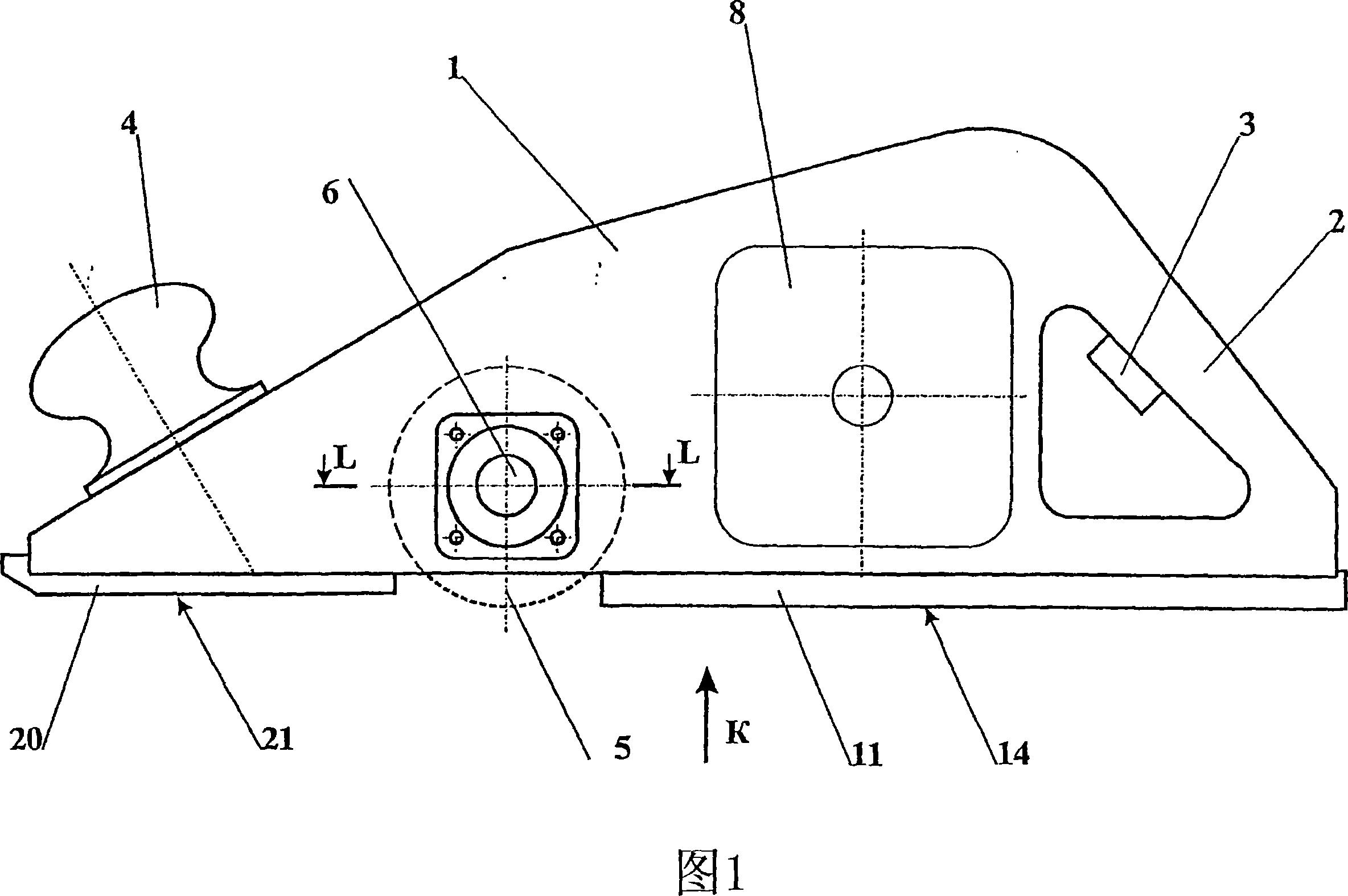
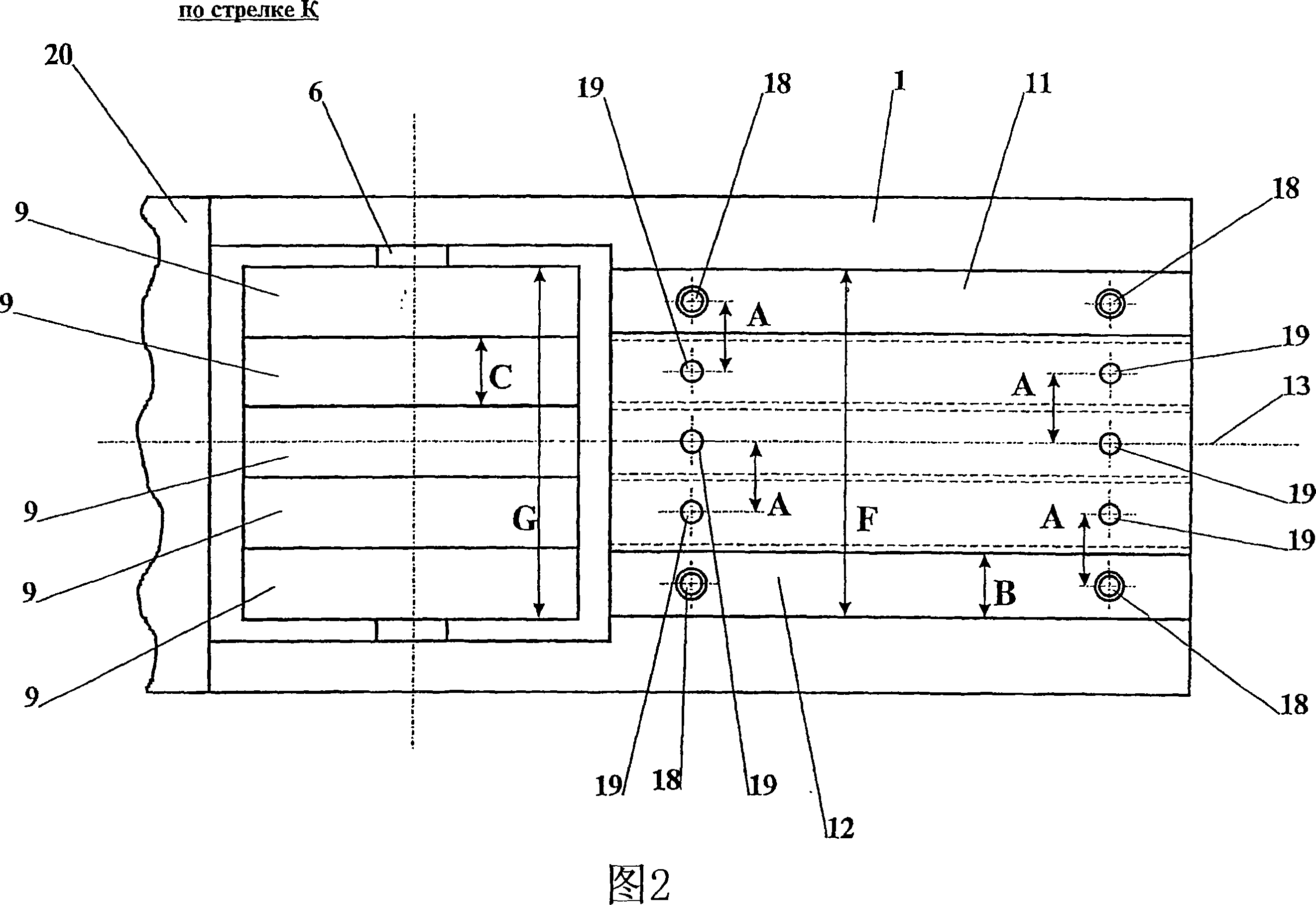
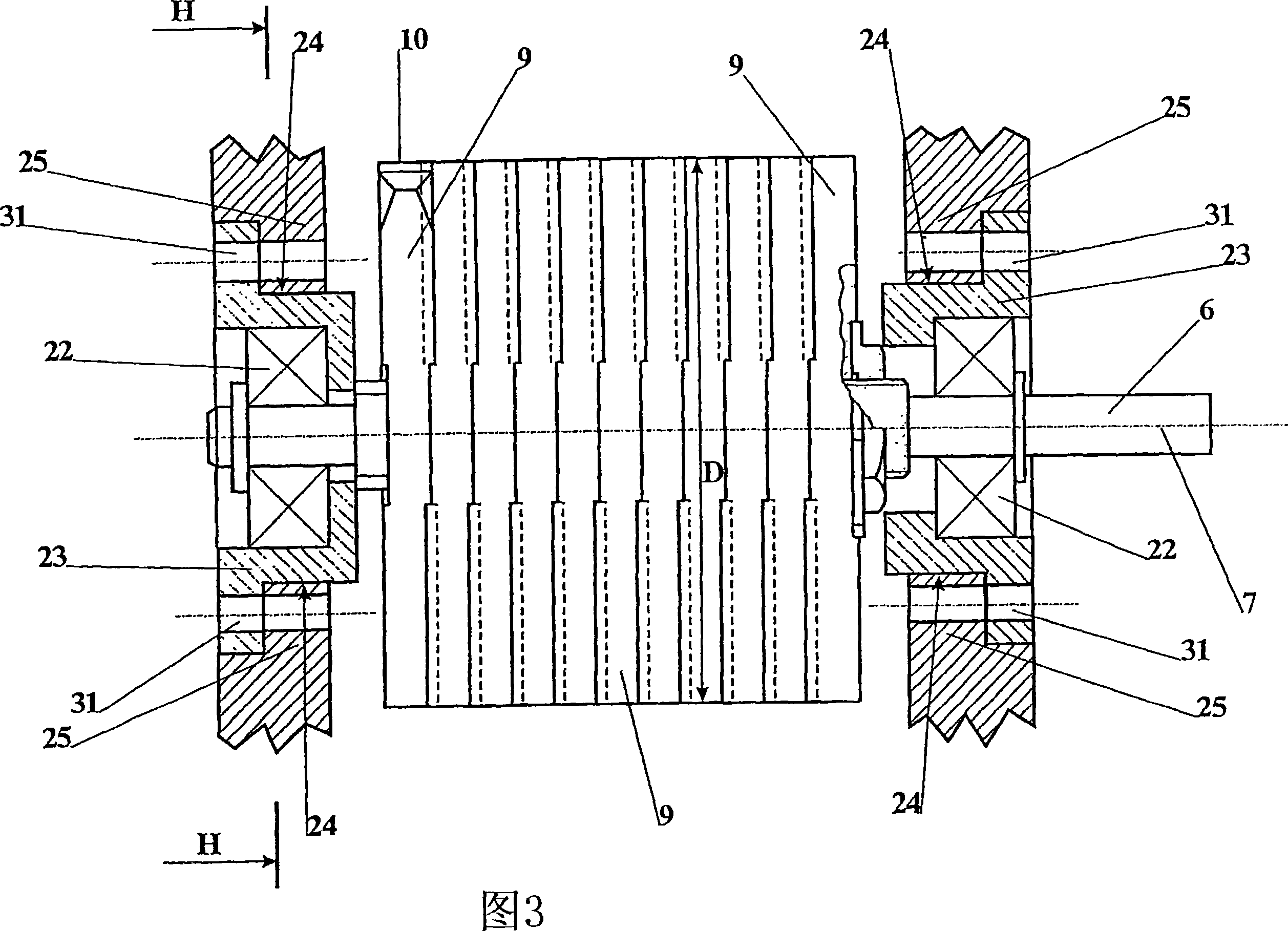
[0023] The motor planer comprises a main body part 1 with a rear handle 2 housing an actuating mechanism (not shown) via a trigger 3 , and a front handle 4 . The body part 1 has an area accommodating a cutting head 5 driven by a drive shaft 6 with freedom of rotation about a longitudinally extending axis of symmetry 7 and firmly fastened to the drive shaft 6 by some means. The means for clamping the cutting head 5 on the drive shaft 6 may be provided as any known releasable connection, such as a barbed or keyed joint. The drive shaft 6 is kinematically connected to a motor 8 which is placed in the inner region of the body part 1 . The motor 8 used can be represented by any known motor, such as an electric motor or a compressed air motor. The kinematic connection between the motor 8 and the drive shaft 6 may for example be in the form of a belt drive (not shown). The cutting head 5 ( FIG. 3 ) is in the form of at least two faceted cutters 9 mounted on a drive shaft 6 . Each ...


PUM


Abstract

The invention can be used in woodworking for planing and shaping wood parts. The inventive mechanical plane comprises a body (1), a cutting head (5) and a rear-bearing unit. Said cutting head (5) is placed in the body (1) cavity in such a way that it is rotatable on bearing elements. The cutting head (5) comprises at least two cutters (9) which are mounted on a driving spindel. The rear-bearing unit is embodied in the form of at least two skis (11, 12) which are arranged in a parallel position with respect to the body (1) axis of symmetry and are connected thereto by means of a detachable joint. Said skis (11, 12) are mounted in such a way that they are stepwisely displaceable along the body (1) width. The cutting head (5) is mounted in such a way that it is displaceable on a vertical plane and is fixable at an intermediate position. The body (1) is provided with two grooves which are symmetrically arranged and open on the underside for receiving bearing elements. The length of each groove along the longitudinal axis of symmetry thereof ranges from 0.3 to 0.9 the disc cutter diameter. Said invention makes it possible to extend the plane service life for producing profiled surface having different configuration.

Description

technical field [0001] The present invention relates to the woodworking industry and in particular to a hand powered planer which is used for surface preparation to plan and finish wooden parts. Background technique [0002] As is well known, a motorized planer comprises a body portion having two symmetrically extending grooves open at the bottom, and a cutting head arranged in the inner region of said body portion, the cutting head rotating on a bearing assembly, said cutting head having a The degree of freedom of movement relative to the body part in the vertical plane is clamped at an intermediate position (refer to patent document RU2236346, classification number B27C1 / 10, publication date 2004-09-20). [0003] The prior art is structurally deficient in that it cannot form a surface of a specific shape on the material to be processed, which limits the scope of use of the motorized planer. Furthermore, when creating rectangular grooves in the process material, it is subs...

Claims


Application Information

Patent Timeline
IPC IPC(8): B27C1/10
CPCB27C1/10B27G13/007
Inventor 莱夫·亚历山大维奇·波诺马廖夫维亚切斯拉夫·伊万诺维奇·梅多福尔金
Owner 莱夫·亚历山大维奇·波诺马廖夫
Why Eureka
Try Eureka