Electromagnetic permanent magnet brake

A technology of electromagnetic brake and permanent magnet, applied in the direction of brake type, axial brake, brake actuator, etc., can solve the problems of braking torque limitation, impossible installation space, etc.

Active Publication Date: 2008-01-30
KENDRION VILLINGEN GMBH
View PDF0 Cites 20 Cited by
  • Summary
  • Abstract
  • Description
  • Claims
  • Application Information

AI Technical Summary

Problems solved by technology

Therefore and due to the disc-shaped design of the permanent magnets, the braking torque is limited, since in order to increase the braking torque the radial dimension of the ring-shaped permanent magnet must be increased, which is usually not possible due to the available installation space

Method used


Image

  • Electromagnetic permanent magnet brake
  • Electromagnetic permanent magnet brake

Examples


Embodiment Construction

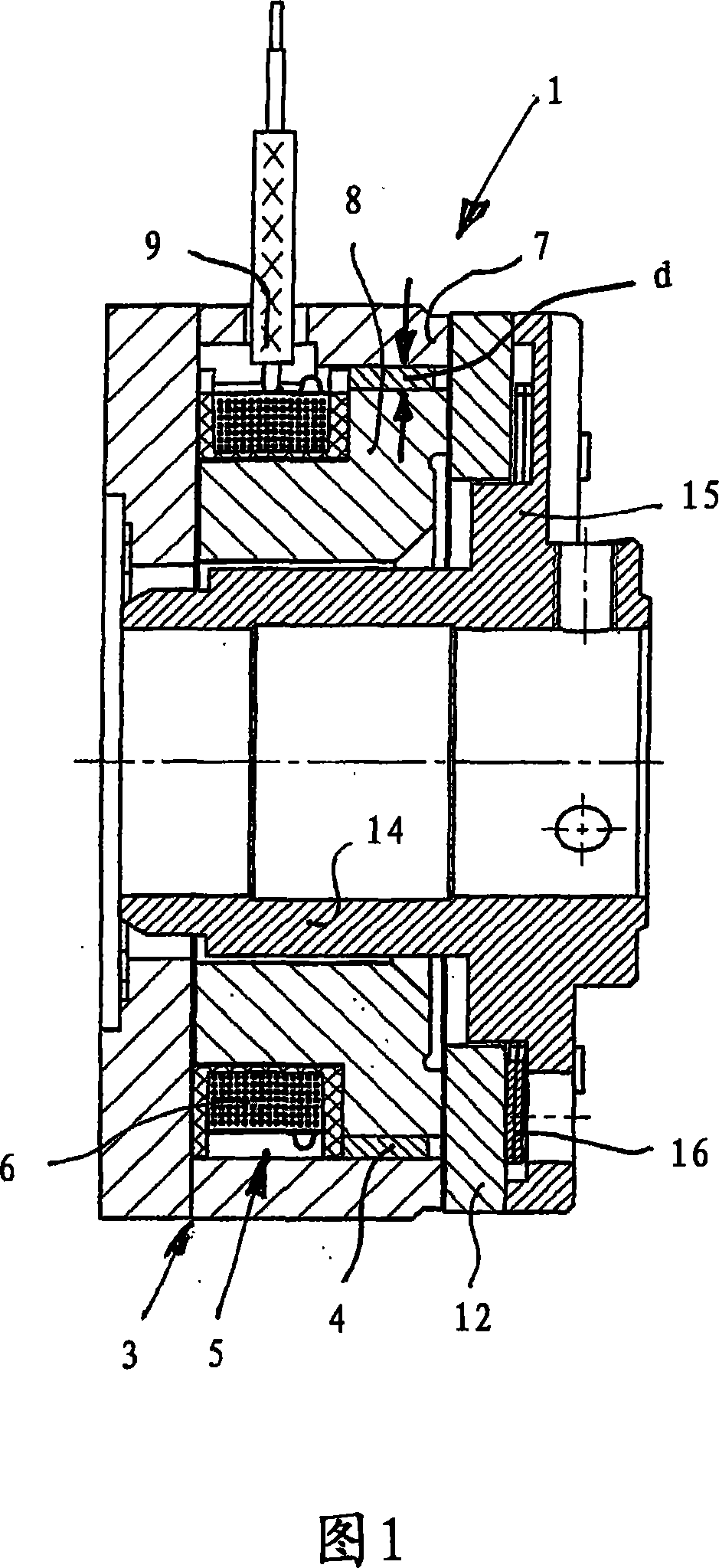
[0032] In the following description of the two exemplary embodiments, parts that are identical in terms of their function are provided with identical reference symbols even if their design and structure differ slightly.

[0033] An electromagnetic brake generally indicated by 1 is considered for an electric drive not shown in detail and has a brake body 3 comprising a permanent magnet 4, at least one electromagnet 5 with an electromagnetic excitation coil 6, a An outer pole of the outer ring 7 and an inner pole of the inner ring 8. The litz wires or plugs 9 connected to the field coil 6 can be seen here from above in FIG. 1 .

[0034] In the position of use, the brake body 3 is connected in a rotationally fixed manner to the frame or housing of the electric drive, for example via a bearing cover in a known manner.

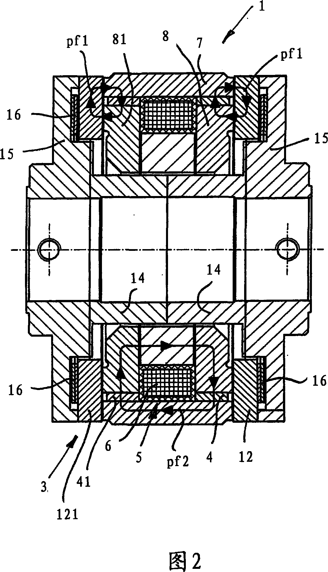
[0035] According to FIG. 1, the electromagnetic brake 1 comprises an armature disc 12, which is connected in a rotationally fixed manner to the rotatable shaft of...


PUM


Abstract

An electromagnetic brake (20), in particular for an electric drive is provided, having a brake body (3), which is provided with a sleeve-shaped permanent magnet (4), an electromagnet (5) with an exciting coil (6), an external ring in the form of an external pole and an internal ring (8) in the form of an internal pole, wherein an armature disc (12) rotatably connected to a shaft is attractable against the brake body (3) or the external or internal ring surfaces by the permanent magnet (4) force acting against a return spring force. When the exciting coil is powered, the permanent magnet (4) magnetic field is compensated in such a way that the armature disc (12) is lifted up from the brake body (3) by the spring force, thereby allowing the brake to be released. A radial cross-sectional dimension or cross-sectional thickness d of the permanent magnet (4) is smaller than the axial dimension thereof and a spatial arrangement, viewed in the axial direction, is provided between the armature disc (12) and the exciting coil (6) in the area radially external with respect to the exciting coil (6) or the housing thereof.

Description

technical field [0001] The invention relates to an electromagnetic brake, in particular for an electric drive, having at least one brake body with at least one permanent magnet, at least one electromagnet with an electromagnetic excitation coil, an outer pole in the form of an outer ring and An inner pole formed as an inner ring, in which the brake body is directly or indirectly connected in a rotationally fixed manner, especially to the support of an especially electric drive; it also has an armature disc, which is directly or indirectly connected to the axis of rotation of the drive Ground rotation and fixed connection, wherein the armature disc forms a magnetic circuit with the outer and inner poles and the permanent magnet through an air gap, wherein the armature disc can be attracted to the brake body by the magnetic force of the permanent magnet against the force of the spring, and the electromagnet When the field coil is energized, the magnetic field of the permanent ma...

Claims


Application Information

Patent Timeline
Patent Type & Authority Applications(China)
IPC IPC(8): F16D65/14F16D55/00F16D65/18
CPCF16D2129/065F16D2121/22F16D55/02
Inventor J·贝恩特E·梅斯纳D·伯切尔
Owner KENDRION VILLINGEN GMBH
Why Eureka
Try Eureka