Tension rod type hanging and height adjusting mechanism

A height-adjusting, pull-rod-type technology, applied in the field of new adjustment mechanisms, can solve problems affecting the speed and stability of rail vehicles, power consumption, and affecting linear motors, etc., to achieve shortened maintenance time, excellent dynamic performance, and reasonable suspension systems Effect

Active Publication Date: 2008-02-06
CRRC QINGDAO SIFANG CO LTD
View PDF0 Cites 13 Cited by
  • Summary
  • Abstract
  • Description
  • Claims
  • Application Information

AI Technical Summary

Problems solved by technology

For the linear motor bogie, it is required to reduce the vertical movement of the linear motor relative to the track induction plate as much as possible, and from the design point of view of improving the comfort of the train, it is required that the overall frame has a certain amount of ups and downs. There is a contradictory relationship between the linear motor fixing method and the bogie fixed connection structure
[0004] Due to the design defect of the above-mentioned existing linear motor and bogie integrated connection structure, when the wheel becomes small due to long-term wear and tear, the vertical height of the linear motor changes and its height cannot be adjusted randomly. The vertical distance between the induction plates exceeds the specified range, which affects the traction force of the linear motor on the bogie, reduces the running speed of the rail vehicle, and consumes part of the electric energy needlessly
[0005] To sum up the above-mentioned problems affecting the speed and stability of rail vehicles, the linear motor of the existing bogie adopts an integrated connection structure, and the vertical height of the linear motor cannot be adjusted arbitrarily according to the wear of the wheels

Method used


Image

  • Tension rod type hanging and height adjusting mechanism
  • Tension rod type hanging and height adjusting mechanism
  • Tension rod type hanging and height adjusting mechanism

Examples


Embodiment 1

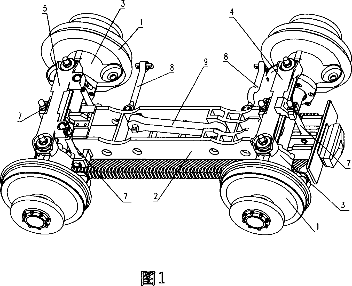
[0058] Embodiment 1, as shown in Figures 1 to 7, the tie rod type suspension and height adjustment mechanism of the present invention is provided with a transverse support beam 4 and a transverse support beam 5 on the two axle boxes 3 of the front and rear wheel sets 1, respectively. .

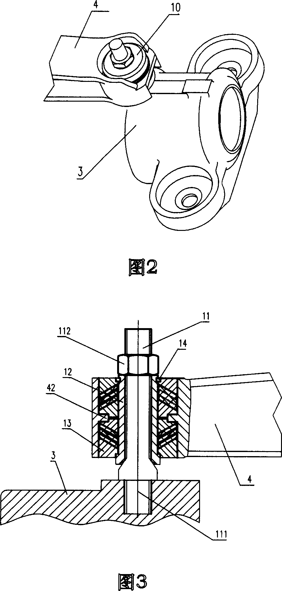
[0059] The end of the support beam is connected and supported on the axle box by the connecting mechanism 10.

[0060] In this embodiment, each bogie adopting a linear traction motor is equipped with a linear motor 2. Each linear motor 2 is suspended and connected by a lateral support beam 4 and a lateral support beam 5, and five vertical tie rods 7, so that the linear motor 2 is installed at the center of the axle.

[0061] As shown in FIG. 1, two vertical tie rods 7 symmetrically hang the inner and outer central parts of the lateral support beam 4.

[0062] The three vertical tie rods 7 hang the inside and outside of the lateral support beam 5 in a "pin" shape.

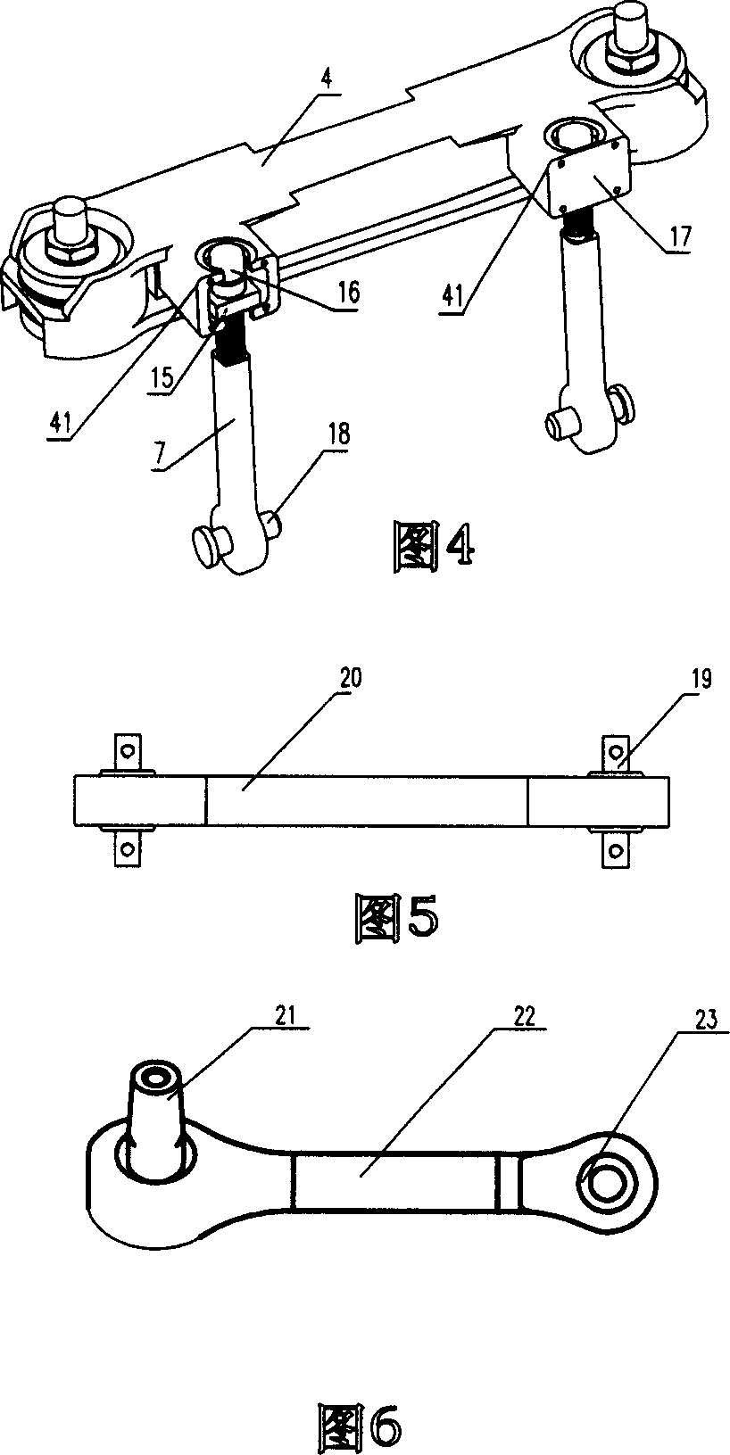
[0063] As shown in FIG. 4, a mou...


PUM


Abstract

The tie rod type hanging and height adjustment mechanism of the invention adopts a special separate type design in the vertical direction of the movement between a linear motor and a truck frame, and the tie rod type hanging and height adjustment mechanism is arranged at the joint between the linear motor and a supporting beam. An elastic connection between the supporting beam and the axle box of front and rear wheel pairs is adopted to provide the hanging elasticity of the linear motor and realize the bending and twisting of the truck within an allowable range. When height adjustment is required, the linear motor can be adjusted through the height adjustment mechanism to enable the clearance between the linear motor and a rail induction board to meet design requirements. That is to say, the linear motor can be adjusted to any required height within the wheel wear range. The invention not only realizes simple and stepless adjustment of the linear motor but also reduces the maintenance time of railway vehicles to the farthest degree. Additionally, the invention also ensures the tractive of the linear motor on the truck and the high-speed running of railway vehicles.

Description

Technical field [0001] The invention relates to a novel adjustment mechanism for a rail vehicle bogie, in particular to realize a fixed connection of a linear motor through a tie rod type suspension and a height adjustment mechanism. Background technique [0002] With the rapid development of my country's society and economy, it is imperative to increase the speed of trunk railways and the development of urban rail transit. The high-speed operation of rail vehicles puts forward higher design requirements for the stability of the bogie structure and service performance. [0003] The bogie of a rail vehicle is a rigid frame that fixes the front and rear wheelsets. In the existing bogies that use linear motors as traction power, the linear motors are usually bolted to the frame of the vehicle bogie. For the linear motor bogie, it is required to minimize the vertical movement of the linear motor relative to the track induction plate, and from the perspective of improving the comfort ...

Claims


Application Information

Patent Timeline
Patent Type & Authority Applications(China)
IPC IPC(8): B61F5/26B61C3/00
Inventor 周平宇李言义张雄飞
Owner CRRC QINGDAO SIFANG CO LTD
Why Eureka
Try Eureka