Cogeneration system

A technology of combined heat and power generation and thermal energy, which is applied in the energy industry, combined combustion mitigation, heating/cooling equipment, etc., and can solve problems such as reduced system reliability, easy temperature rise, and abnormal printed circuit boards

Inactive Publication Date: 2008-02-06
INTELLECTUAL DISCOVERY CO LTD
View PDF0 Cites 11 Cited by
  • Summary
  • Abstract
  • Description
  • Claims
  • Application Information

AI Technical Summary

Problems solved by technology

[0015] However, the combined heat and power system in the prior art has such a shortcoming: when the engine room (E) is at a high temperature due to the heat energy emitted by the engine 4 itself, the temperature inside the control box 22 is easily increased, causing the control box 22 to Abnormal operation of the internal printed circuit board (PCB), resulting in reduced reliability of the system, because the engine 4, generator 2 and control box 22 are installed in one engine room (E) formed by the chassis

Method used


Image

  • Cogeneration system
  • Cogeneration system
  • Cogeneration system

Examples


Embodiment Construction

[0041] Preferred embodiments of the present invention will be described in more detail below with reference to the accompanying drawings.

[0042] The combined heat and power system according to the embodiments of the present invention can be arranged in various ways, the most desirable embodiment of which will be described below.

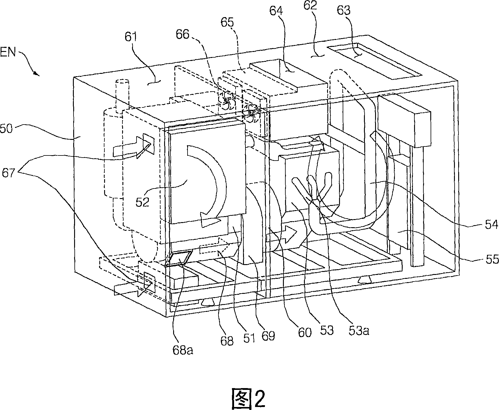
[0043] FIG. 2 is a perspective view showing a cogeneration unit according to a first embodiment of the present invention.

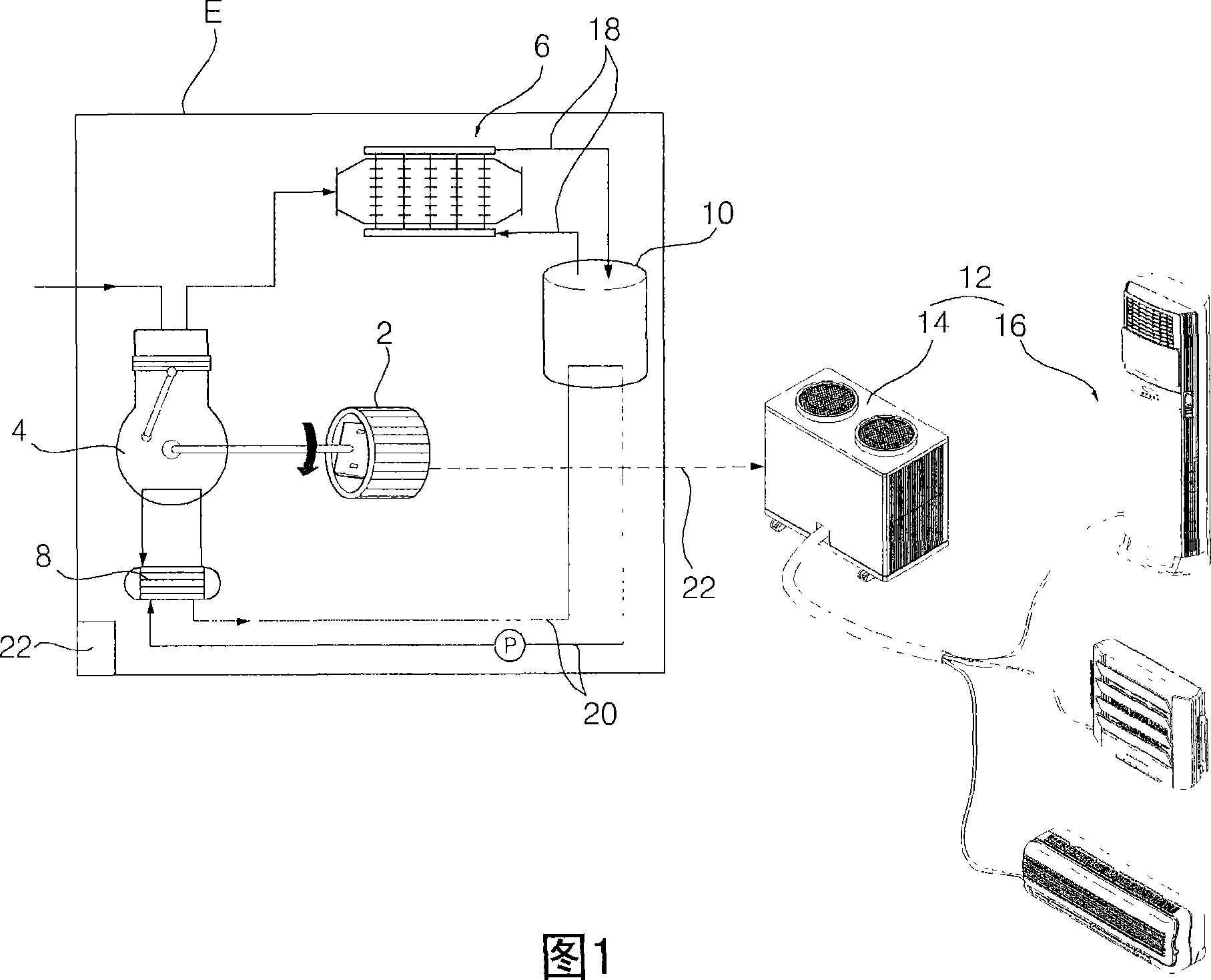
[0044] As shown in FIG. 2, the cogeneration system according to the first embodiment of the present invention includes: a built-in cogeneration unit for generating electric energy and heat energy; a thermal energy target unit (not shown) using the cogeneration unit Generated electricity and heat.

[0045] The thermal energy target unit (not shown) may be a heat pump air conditioner operating in an air conditioning mode or a heating mode, or may also be a hot water supply tank.

[0046] The cogeneration unit includes: a gener...


PUM


Abstract

Provided is a cogeneration system. The system includes a chassis, a controller cooling unit, and a driver cooling unit. The chassis is provided with a generator, a driving source, a waste heat recovering unit, and a controller. The generator generates power. The driving source drives the generator and generates heat. The waste heat recovering unit recovers a waste heat of the driving source. The controller controls operations of the generator, the driving source, and the waste heat recovering unit. The controller cooling unit introduces air at one side inside the chassis, circulates the introduced air, and cools at least any one of the generator and the controller. The driver cooling unit introduces air at the other side inside the chassis, circulates the introduced air, and cools at least any one of the driving source and the waste heat recovering unit.

Description

technical field [0001] The present invention relates to a combined heat and power system, and more particularly, to a combined heat and power system for preventing a controller from being overheated by thermal energy generated in an engine, thereby improving reliability and efficiency. Background technique [0002] In general, a combined heat and power system refers to a system that simultaneously generates electricity and heat from a single energy source. [0003] FIG. 1 is a schematic diagram of a cogeneration system in the prior art. [0004] As shown in Figure 1, the cogeneration system in the prior art includes: a generator 2 for generating electric energy; a driving source (hereinafter referred to as "engine"), such as an engine 4, for driving the generator 2, and generating thermal energy; a waste heat recovery unit for recovering waste heat generated in the engine 4; a heat destination unit (heat destination) 10, such as a heat energy storage tank, utilizing the was...

Claims


Application Information

Patent Timeline
Patent Type & Authority Applications(China)
IPC IPC(8): F02G5/04F01P1/00F01P5/06
CPCF02G2262/00Y02T10/166F01P7/04B60H1/00421F02B63/04F25B27/02F01P2001/005F02G5/04Y02E20/14Y02T10/12Y02P80/15Y02A30/274F01B23/10F01B31/08
Inventor 赵南俊金亨寿黄本昌
Owner INTELLECTUAL DISCOVERY CO LTD
Why Eureka
Try Eureka