Eureka AIR delivers breakthrough ideas for toughest innovation challenges, trusted by R&D personnel around the world.

High performance kinetic spray nozzle

A technology of power spraying and nozzle, applied in the direction of spraying device, spraying device, liquid spraying device, etc.

Inactive Publication Date: 2008-02-13
DELPHI TECH INC
View PDF4 Cites 11 Cited by
  • Summary
  • Abstract
  • Description
  • Claims
  • Application Information

AI Technical Summary

Problems solved by technology

However, there are limiting factors in the achievable velocities of heated gas streams within power spray systems

Method used


Image

  • High performance kinetic spray nozzle
  • High performance kinetic spray nozzle
  • High performance kinetic spray nozzle

Examples


Embodiment Construction

[0019] The present invention includes references to, for example, U.S. Patent Application No. 2005 / 0214474A1, U.S. Patent Nos. 6,139,913 and 6,283,386, and Van Steenkiste et al., published Jan. 10, 1999 in Surface and Coatings Technology, volume III, pp. 62-72. Improvements made to the power spray system and nozzle assembly 20 are primarily described in the document entitled "Power Spray Coating". The disclosures of all of the above documents are hereby incorporated by reference.

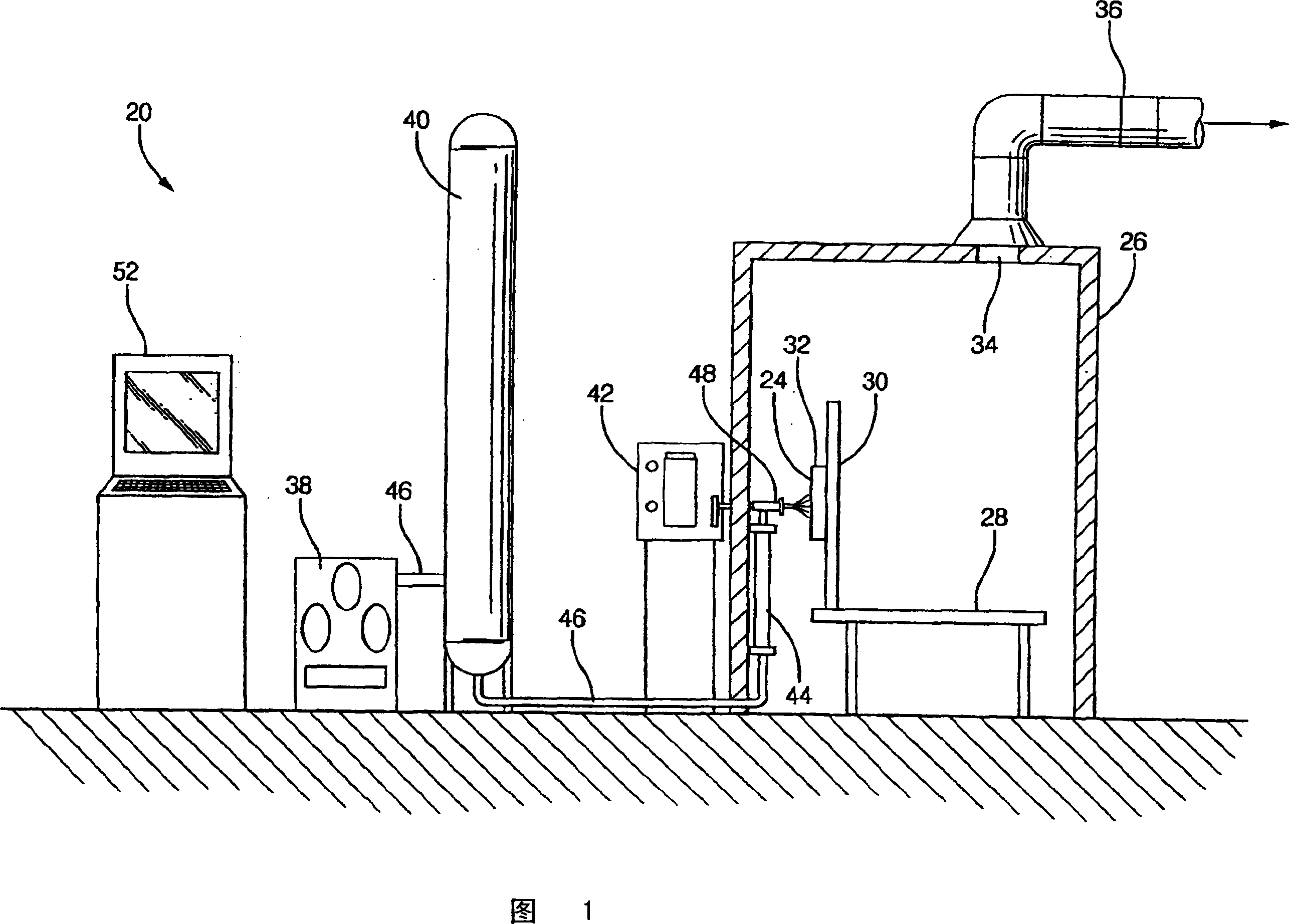
[0020] Referring to the drawings in which like reference numerals are used to indicate corresponding parts, the power spray system is generally indicated by the reference numeral 20 . Referring to FIG. 1 , a powered spray system 20 applies a coating of powder particles 22 to a substrate material 24 . The heated gas stream suspends powder particles 22 which are then sprayed onto substrate material 24 at high velocity. As disclosed in U.S. Patent No. 6,139,913, base material 24 may comprise any of a...


PUM


Abstract

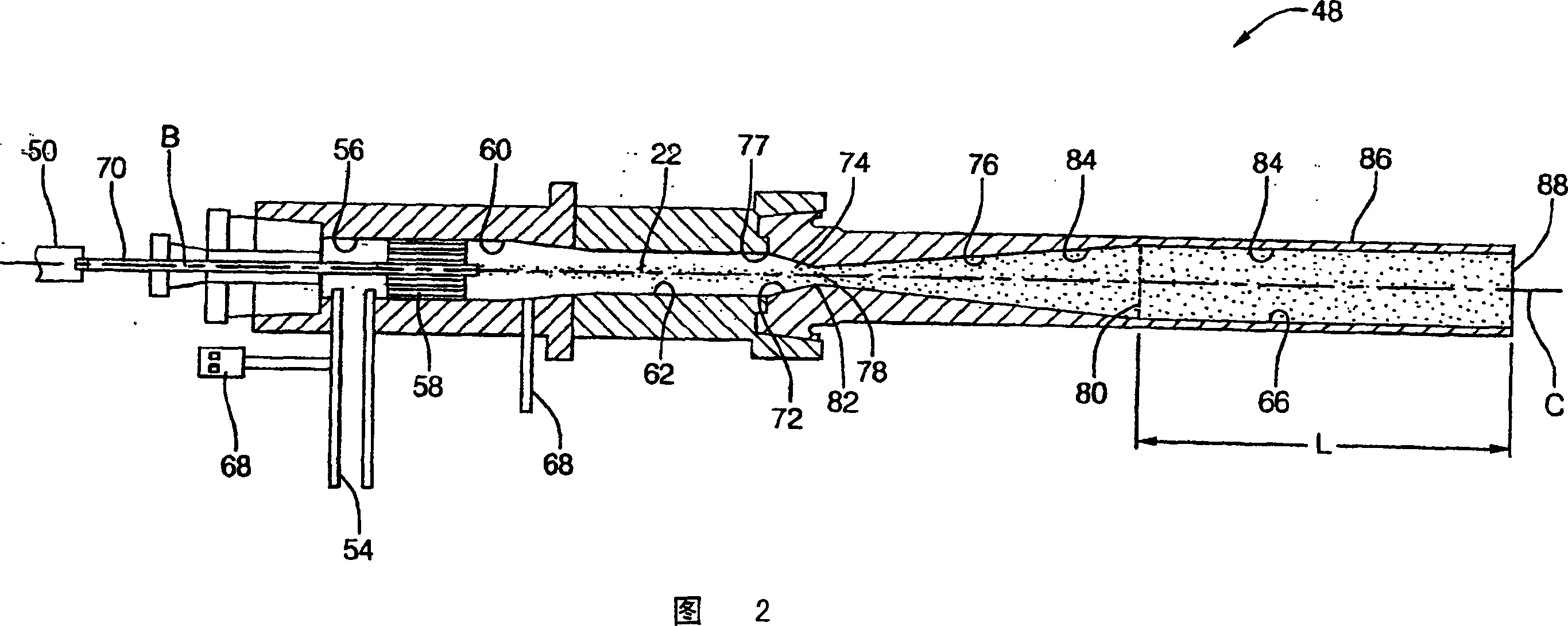
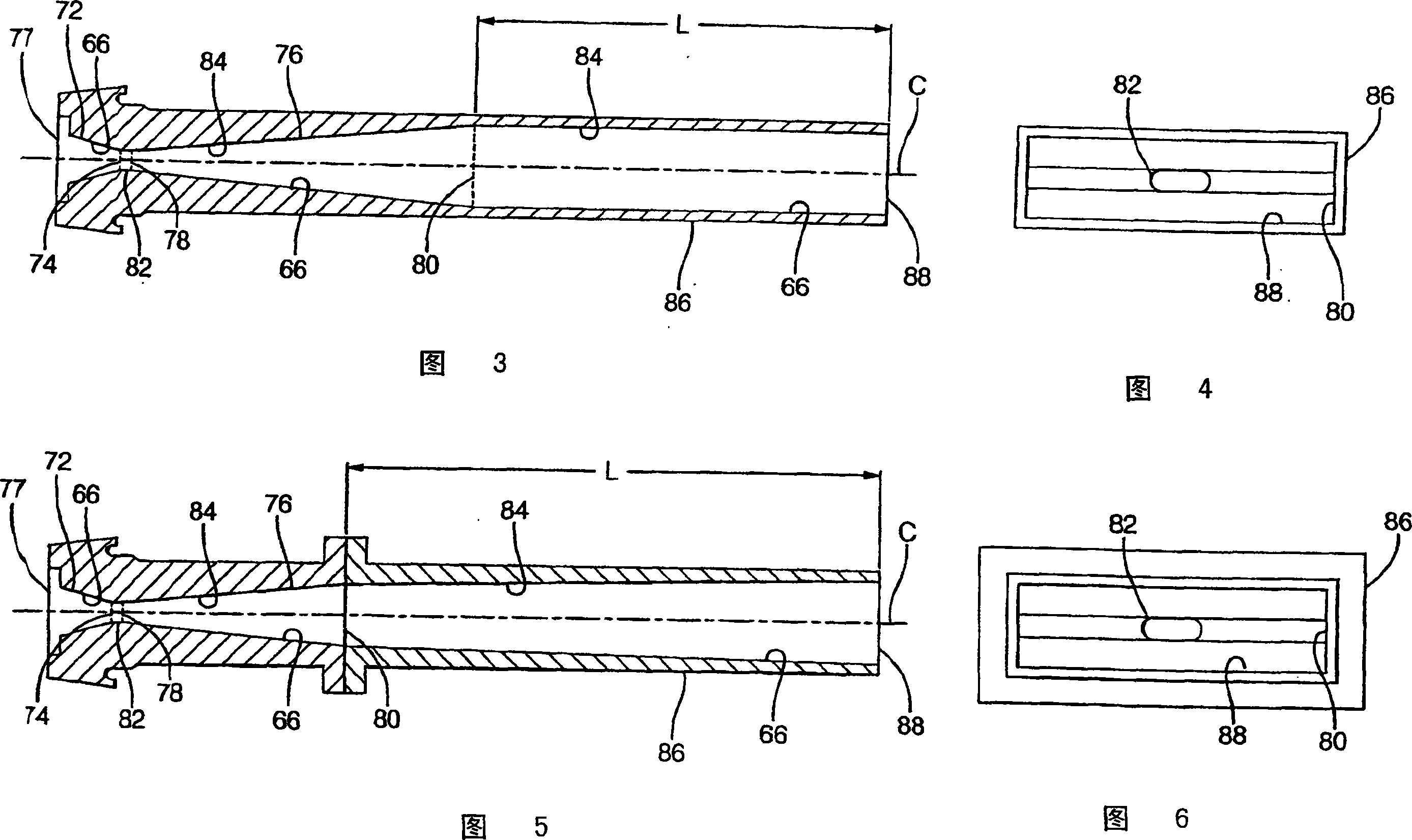
A nozzle assembly (48) for a kinetic spray system includes a convergent portion (72) , a throat portion (82) , and a divergent portion (76) , each cooperating together to define a passage (66) therethrough for passing a mixture of powder particles (22) suspended in a flow of a high pressure heated gas. The nozzle assembly (48) further includes an extension portion (86) attached to the divergent portion (76) and extending to a distal end (88) a pre-determined length (L) from the divergent portion (76) of the nozzle assembly (48) . The extension portion (86) permits a dragging force exerted on the powder particles (22) by the flow of high pressure heated gas to act upon the powder particles (22) for a longer duration of time, thereby permitting the powder particles (22) to accelerate to a greater velocity than has been previously achievable.

Description

[0001] This application is a continuation-in-part of USSN 10 / 924270 filed August 23,2004. technical field [0002] The present invention generally relates to nozzle assemblies for power spray systems. Background technique [0003] Nozzle assemblies for powered spray systems typically include a mixing chamber for mixing a stream of powder particles with a stream of heated gas under positive pressure conditions. The mixing chamber is connected to a Laval-type convergent-divergent ultrasonic nozzle. The heated gas is also introduced into the mixing chamber under positive pressure which is set lower than that of the flow of powder particles. In the mixing chamber, the stream of heated gas is mixed with the stream of powder particles to form a gas / powder mixture. The gas-powder mixture flows from the mixing chamber into an ultrasonic nozzle in which the powder particles are accelerated to velocities from 200 to 1,300 m / s. [0004] U.S. Patent Application No. 2005 / 0214474A1 (he...

Claims


Application Information

Patent Timeline
Patent Type & Authority Applications(China)
IPC IPC(8): B05B1/00B05B1/24B05B12/00B05B7/00B05B7/24B05D1/12
CPCB05B7/1613C23C24/04B05B7/1486B05B1/044B05B1/02B05B1/26
Inventor Z·赵B·A·吉里斯皮T·韩A·A·伊尔默斯N·B·帕特尔
Owner DELPHI TECH INC
Why Eureka
Eureka Blog
Learn More