Rotating gate

A technology of revolving doors and door wings, which is applied in the field of revolving doors, can solve problems such as inconvenient use, narrow passages, obstacles in revolving doors, etc., and achieve the effect of avoiding crowded accidents

Active Publication Date: 2008-02-13
北京宝盾门业技术有限公司
View PDF1 Cites 7 Cited by
  • Summary
  • Abstract
  • Description
  • Claims
  • Application Information

AI Technical Summary

Problems solved by technology

However, each of the above-mentioned passages is relatively narrow, and there are still obstacles when people pass through the revolving door in an

Method used


Image

  • Rotating gate
  • Rotating gate
  • Rotating gate

Examples


Embodiment Construction

[0035] Specific embodiments of the present invention will be described in detail below in conjunction with the accompanying drawings.

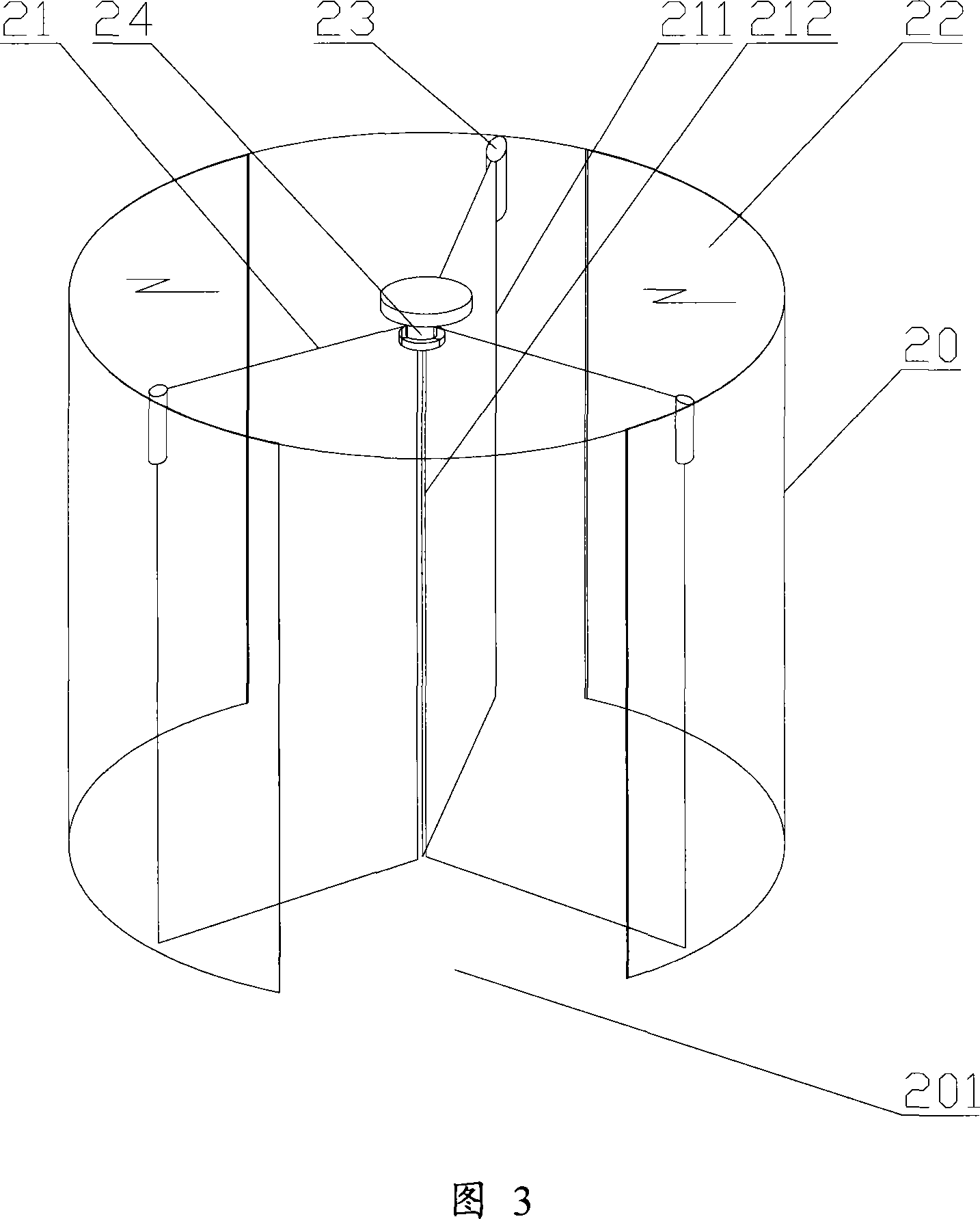
[0036] Please refer to Fig. 3 and Fig. 4 first. Fig. 3 is a structural diagram of the first embodiment of the revolving door according to the present invention; Fig. 4 is a schematic diagram of the installation method of the revolving door wing shown in Fig. 3 . In the first embodiment of the revolving door of the present invention, the revolving door includes a cylindrical wall 20 provided with two corresponding openings 201, and the cylindrical wall 20 can usually be made of a transparent material. A passage for a revolving door for pedestrians to pass through may be formed between the two openings 201 . The revolving door also includes a top plate 22 and several door wings 21, and the door wings 21 are usually also made of transparent materials. The revolving door provided by the first embodiment of the revolving door of the present invent...


PUM


Abstract

The invention discloses a rotary door, which comprises two drum-shaped walls opened for passing; a plurality of door wings and a top plate rotating together with the door wings; the top of the first side edge of the door wings is provided with a first rotary axle; the door wings is connected to the top plate near the drum-shaped walls through the first rotary axle by pivots; a lock device is arranged between the second side edge of the door wings and the top plate; the lock device locks the door wings when the rotary door rotates normally; the door wings of the rotary door provided by the invention can rotate around the first rotary axle and open from the center of the rotary door; thereby providing a wide passage for people to evacuating on emergency and also passing huge articles and minibuses.

Description

technical field [0001] The invention relates to a revolving door, in particular to a revolving door without a center revolving column. Background technique [0002] Existing revolving doors generally include a cylindrical wall with two openings, a lower turntable installed at the center of the ground, an upper turntable installed at the center of the top, and a central column as the center of rotation of the revolving door and fixed at the center. Several door wings on uprights. The door wing is connected with the center column, and rotates around the center column together with the upper and lower turntables. The user can push the door wing to rotate around the center column through the opening on the cylinder wall to enter and exit the center column. revolving door. Since the door wings are usually fixed to the immovable central upright, no quick escape route is provided in case of an emergency. [0003] A utility model patent with the authorized notification number of ...

Claims


Application Information

Patent Timeline
IPC IPC(8): E06B3/90E05F15/10E05F15/608
Inventor 费向红林自立
Owner 北京宝盾门业技术有限公司
Why Eureka
Try Eureka