Rotary ultrasonic motor and its implementation method

An ultrasonic motor and rotary technology, applied in the field of electric motors, can solve the problems of low driving force, high cost, and increased cost, and achieve high torque, self-locking force when power is off, large driving force, and good stability

Inactive Publication Date: 2008-02-13
SOUTH CHINA AGRI UNIV
View PDF2 Cites 13 Cited by
  • Summary
  • Abstract
  • Description
  • Claims
  • Application Information

AI Technical Summary

Problems solved by technology

[0002]In the existing rotary ultrasonic motors, the cylindrical stator is mainly used, and one end of the rotor matched with the stator is an inner cylindrical surface, and it is a single rotor output. There are common defects of complex processing technology and low driving force
The "miniature rod type traveling wave ultrasonic motor" with the patent number "200410065703.9" relies on the end surface friction contact between the stator and the rotor. The difference in relative speed between them, the degree of wear of the contact area of ​​the inner and outer rings is different, the output torque of the rotor is related to the area of ​​the disc surface or torus in the contact area, and the maximum output torque has not yet been reached; in addition, piezoelectric ceramics adopt Two partitions, in order to produce the

Method used


Image

  • Rotary ultrasonic motor and its implementation method

Examples


Embodiment

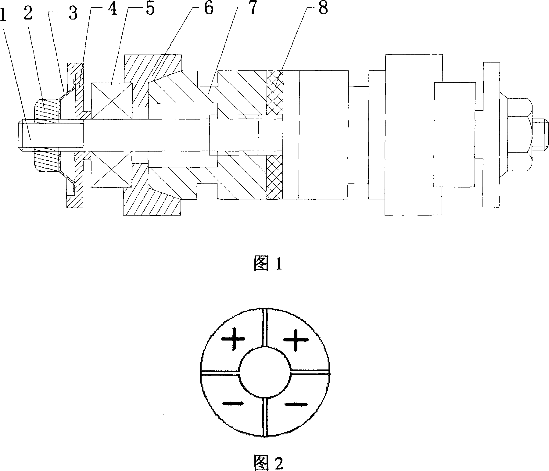
[0018] As shown in Figure 1, a double-rotor rotary ultrasonic motor is symmetrically arranged on the screw 1 with a set nut 2, a disc spring 3, a tray 4, a bearing 5, a rotor 6, a stator 7, and a piezoelectric ceramic sheet 8 , the piezoelectric ceramic sheet 8 is fixed in the middle of the screw rod 1 by threads, the stator 7 is fixed on the screw rod 1 by threads, the end of the stator 7 adjacent to the rotor 6 is a conical surface, and the end adjacent to the rotor 6 and the stator 7 is a conical surface. The inner conical face of the face mate. The bearing 5 is adjacent to the rotor 6 , the disc spring 3 presses the bearing 5 through the tray 4 to press the conical surface, and the set nut 2 adjusts the preload of the disc spring 3 . The screw 1, the set nut 2, the disc spring 3, the tray 4 and the bearing 5 constitute the preload applying system of the motor, and the preload applied to the rotor 6 is adjusted by adjusting the deformation of the disc spring 3 at both ends....


PUM


Abstract

The invention discloses a rotary ultrasonic motor, which comprises a screw, a hold-down mechanism, a bearing, a rotor, a stator and a piezoelectric element. The screw is provided with the piezoelectric element, the stator, the rotor, the bearing and the hold-down mechanism in turn. The piezoelectric element, the stator, and the hold-down mechanism are fixed on the screw. One end of the stator adjacent to the rotor is a circular conical surface. One end of the rotor adjacent to the stator is a female conical surface matched with the circular conical surface. The invention also discloses the method to achieve the rotary ultrasonic motor. The motor has the advantages of direct drive, being well controlled, no noise, no magnetic field action and so on, and is in particular applicable for minitype rotary motion devices of small torsion and multi-rotor output.

Description

technical field [0001] The invention relates to the motor technology utilizing the piezoelectric effect, in particular to a rotary ultrasonic motor and its realization method. Background technique [0002] In the existing rotary ultrasonic motors, the cylindrical stator is mainly used, and one end of the rotor matched with the stator is an inner cylindrical surface, and the output is a single rotor, which generally has the defects of complicated processing technology and low driving force. The "miniature rod type traveling wave ultrasonic motor" with the patent number "200410065703.9" relies on the end surface friction contact between the stator and the rotor. The difference in relative speed between them, the degree of wear of the contact area of ​​the inner and outer rings is different, the output torque of the rotor is related to the area of ​​the disc surface or torus in the contact area, and the maximum output torque has not yet been reached; in addition, piezoelectric ...

Claims


Application Information

Patent Timeline
IPC IPC(8): H02N2/10
Inventor 张铁民
Owner SOUTH CHINA AGRI UNIV
Why Eureka
Try Eureka