Braking equipment for motor vehicles

A technology of braking equipment and motor vehicles, applied in the direction of brakes, vehicle components, brake transmissions, etc.

Inactive Publication Date: 2008-02-13
CONTINENTAL TEVES AG & CO OHG
View PDF1 Cites 19 Cited by
  • Summary
  • Abstract
  • Description
  • Claims
  • Application Information

AI Technical Summary

Problems solved by technology

In the braking system of the prior art, it is considered to be disadvantageous that it is only possible to support driving by the vehicle when the electronics and the energy supply devices (battery and body network) present in the vehicle are active. operator's operating force

Method used


Image

  • Braking equipment for motor vehicles

Examples


Embodiment Construction

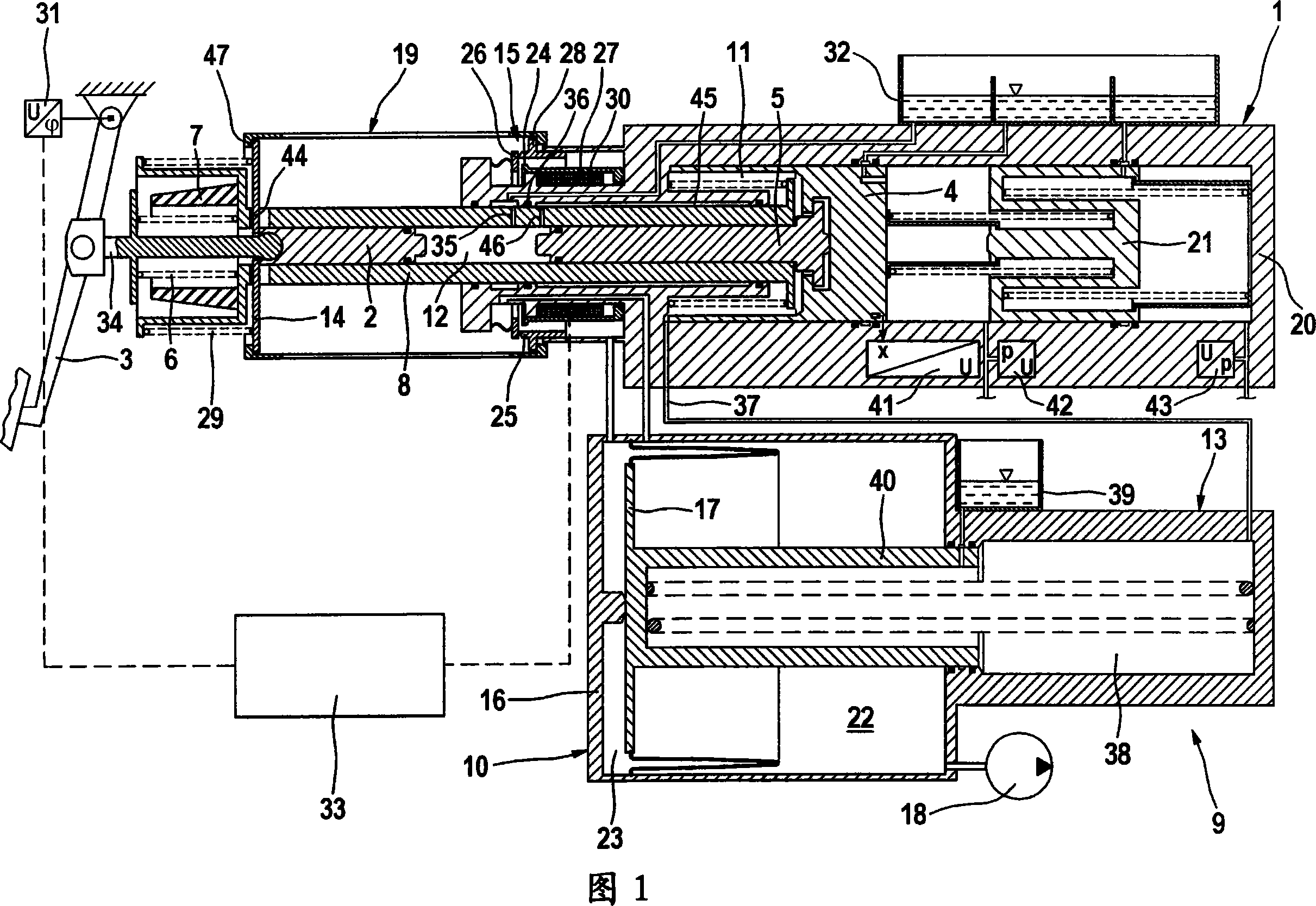
[0035] The brake system according to the invention shown in the figures has a brake pedal 3 which is operatively connected to the first piston 2 via an operating rod 34 . The brake pedal stroke can be detected by a rotational angle sensor 31 . Furthermore, a second piston 4 is provided, which is the actuating piston of master brake cylinder 1 . In the example shown, the master actuating cylinder 1 is designed as a tandem master cylinder, in whose master cylinder housing 20 a further piston 21 is connected to the second piston 4 . The wheel brakes of the vehicle can be connected to master brake cylinder 1 via a controllable wheel brake pressure modulation module, not shown, wherein an electronic control unit and regulating unit, also not shown, is assigned to the wheel brakes. Pressure modulation module. As an alternative or in addition to the angle of rotation sensor shown, a travel sensor can be provided which detects the actuation travel of the push rod 34 or of the first ...


PUM


Abstract

The invention relates to a braking system comprising: a master cylinder (1) and a master cylinder housing (20), to which wheel-brake cylinders can be connected; a first piston (2), which is coupled to a brake pedal (3) via a pressure rod (34) that transmits actuating forces; a second piston (4), which is used to actuate the master cylinder (1); a third piston (5), which can be hydraulically actuated by the first piston (2); at least one elastic element (6, 7), which forms a pedal travel simulator and which during the brake-by-wire mode gives the vehicle driver a comforting pedal sensitivity; elements for coupling the displacement of the first (2) and the third piston (5); an intermediate chamber (11) that can be subjected to a hydraulic pressure, the influence of the latter causing a hydraulic force to act on the second (4) and third piston (5); and an electrically controlled pressure-provision module (9), which permits the intermediate chamber (11) to be filled with hydraulic fluid and to be evacuated. The aim of the invention is to assist the actuating force even when the electronic controller or the electric energy supply fails. To achieve this, the system is equipped with a fourth piston (8), which can be subjected to two opposing forces by means of the elastic element (6, 7) on the input side and the hydraulic pressure in the intermediate chamber (11) on the output side, and elements (14,19,15) that allow the pressure-provision module (9), in addition to being electrically controlled, to be controlled in accordance with the position of the fourth piston (8), obtained by the aforementioned exertion of forces.

Description

technical field [0001] The invention relates to a braking system for a motor vehicle comprising: [0002] a master cylinder with a master cylinder housing to which the wheel brake cylinders can be connected, [0003] a first piston, which is coupled to the brake pedal via a push rod transmitting an operating force, [0004] a second piston for operating the master cylinder, [0005] a third piston hydraulically operable by the first piston, [0006] at least one elastic element forming a pedal travel simulator which provides a pleasant pedal feel for the driver of the vehicle in the "brake-by-wire" operating mode, [0007] means for coupling the movement of the first piston and the third piston, [0008] an intermediate space available for hydraulic pressure, the pressurization of which produces hydraulic pressure on the second and third pistons, and [0009] An electrically controlled pressure supply module may be used which enables both filling and emptying of the inter...

Claims


Application Information

Patent Timeline
Patent Type & Authority Applications(China)
IPC IPC(8): B60T8/40B60T13/14
CPCB60T13/146B60T8/4077B60T8/40B60T13/14
Inventor S·德鲁姆
Owner CONTINENTAL TEVES AG & CO OHG
Why Eureka
Try Eureka