Hydraulic buffering device when automobile being bounced

A hydraulic buffer, automotive technology, applied in the direction of liquid shock absorbers, bumpers, etc., can solve the problems of increasing the failure probability of hydraulic buffer devices, complex structure of hydraulic buffer devices, etc.

Inactive Publication Date: 2008-02-20
李正才
View PDF0 Cites 25 Cited by
  • Summary
  • Abstract
  • Description
  • Claims
  • Application Information

AI Technical Summary

Problems solved by technology

[0002] At present, most of the automobile impact buffer devices are of the type disclosed in the Chinese utility model patent specification 972312072.3, which mainly includes hydraulic columns, steel sleeves, oil pumps, fuel injection chambers, oil storage chambers, spring plugs, etc., and this or has similar structures. After the hydraulic buffer device operates, it needs power equipment such as an oil pump to send the oil sprayed from the oil injection chamber (pressure oil chamber) back to the oil injection chamber. The oil pump and pipeline not only make the structure of the hydraulic buffer device Complicated and increases the chances of failure of the hydraulic shock absorber itself

Method used


Image

  • Hydraulic buffering device when automobile being bounced

Examples


Embodiment Construction

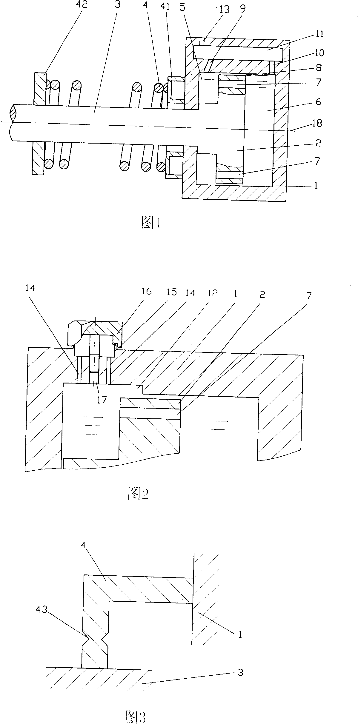
[0013] 1 is a schematic structural diagram of a hydraulic buffer device according to a preferred embodiment of the present invention. The piston cylinder is actually a device assembled from multiple components and sealing materials. The assembly method does not belong to the content of the present invention. For simplicity, Draw it as a whole in the figure. The section through the center line 18 of the piston 2 connected with the piston rod 3 is a convex shape, the piston 2 is placed in the piston cylinder 1, and the cooperation between the piston cylinder 1 and the piston rod 3 is a dynamic fit with an oil sealing function, There is a large gap 8 where the piston cylinder 1 and the piston 2 cooperate, and the internal space formed by the piston cylinder 1, the piston 2 and the piston rod 3 is called the piston cavity. The piston 2 divides the piston cavity into a front cavity 5 and a rear cavity 6. Four communication holes 7 are drilled on the piston 2 at symmetrical position...


PUM


Abstract

The present invention relates to a hydraulic buffering device when the car is hit and consists of a piston cylinder, a piston, a piston rod and a buffering starting device. The coordination of the piston cylinder and the piston rod and the piston are movable fit. The piston cavity that is filled with oil is divided into a front cavity and a back cavity that are communicated by the piston. The oil can not fill the whole space that is communicated with the piston cavity before buffering force of the hydraulic buffering device reaches the maximum design buffering force. The buffering starting device is used for fixing the relative positions of the piston and the piston cylinder. The hydraulic buffering device is actuated and starts the buffering action when the impact of the vehicle reaches a certain design value. The discharged oil in the rear cavity can automatically flow back after the buffering is reset. Better buffering effect can be achieved when the piston cylinder is provided with a vent hole that is communicated with the front cavity and the outside and measures are taken to prevent the oil being discharged out from the vent hole; utilizing spring as the buffering actuating device can realize slow reset of the hydraulic buffering device and the second buffering of the spring.

Description

technical field [0001] The invention relates to an automobile safety device, in particular to a hydraulic buffer device when the automobile is impacted. Background technique [0002] At present, most of the automobile impact buffer devices are of the type disclosed in the Chinese utility model patent specification 972312072.3, which mainly include hydraulic columns, steel sleeves, oil pumps, fuel injection chambers, oil storage chambers, spring bolts, etc., which may have similar structures. After the hydraulic buffer device is activated, it needs to use power equipment such as an oil pump to send the oil ejected from the fuel injection chamber (pressure chamber) back to the fuel injection chamber. The oil pump and pipeline not only make the structure of the hydraulic buffer device becomes more complicated, and also increases the probability of failure of the hydraulic buffer device itself. SUMMARY OF THE INVENTION [0003] The technical problem to be solved by the presen...

Claims


Application Information

Patent Timeline
Patent Type & Authority Applications(China)
IPC IPC(8): B60R19/36
CPCB60R19/32F16F9/18
Inventor 李正才
Owner 李正才
Why Eureka
Try Eureka