Energy-saving type range tray

An energy-saving, stove technology, applied in the direction of stove/stove top, etc., can solve the problems of oxygen-deficient combustion, hindered fire, no flame energy release, etc., to achieve the effect of full combustion, convenient use and simple structure

Inactive Publication Date: 2008-02-20
韩久和 +1
View PDF1 Cites 1 Cited by
  • Summary
  • Abstract
  • Description
  • Claims
  • Application Information

AI Technical Summary

Problems solved by technology

[0005] 1. The diversion baffles arranged in an arc or concentric ring, due to irregularity, cause the combustion path to interfere, collide with each other, hinder the fire pattern, and fail to release the energy of the flame to the maximum extent.
[0006] 2. Due to the above reasons, the fire pattern is uneven and the local temperature at the bottom of the pot is not uniform.
[0007] 3. The flame in the tray burns disorderly, and the supply of air is uneven. In severe cases, it will be in a state of oxygen-deficient combustion. Insufficient combustion leads to energy loss in disguise.

Method used


Image

  • Energy-saving type range tray
  • Energy-saving type range tray
  • Energy-saving type range tray

Examples


Embodiment Construction

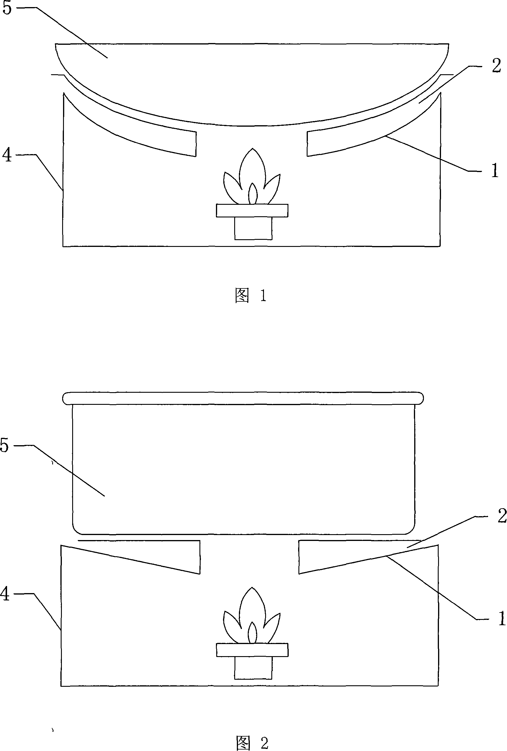
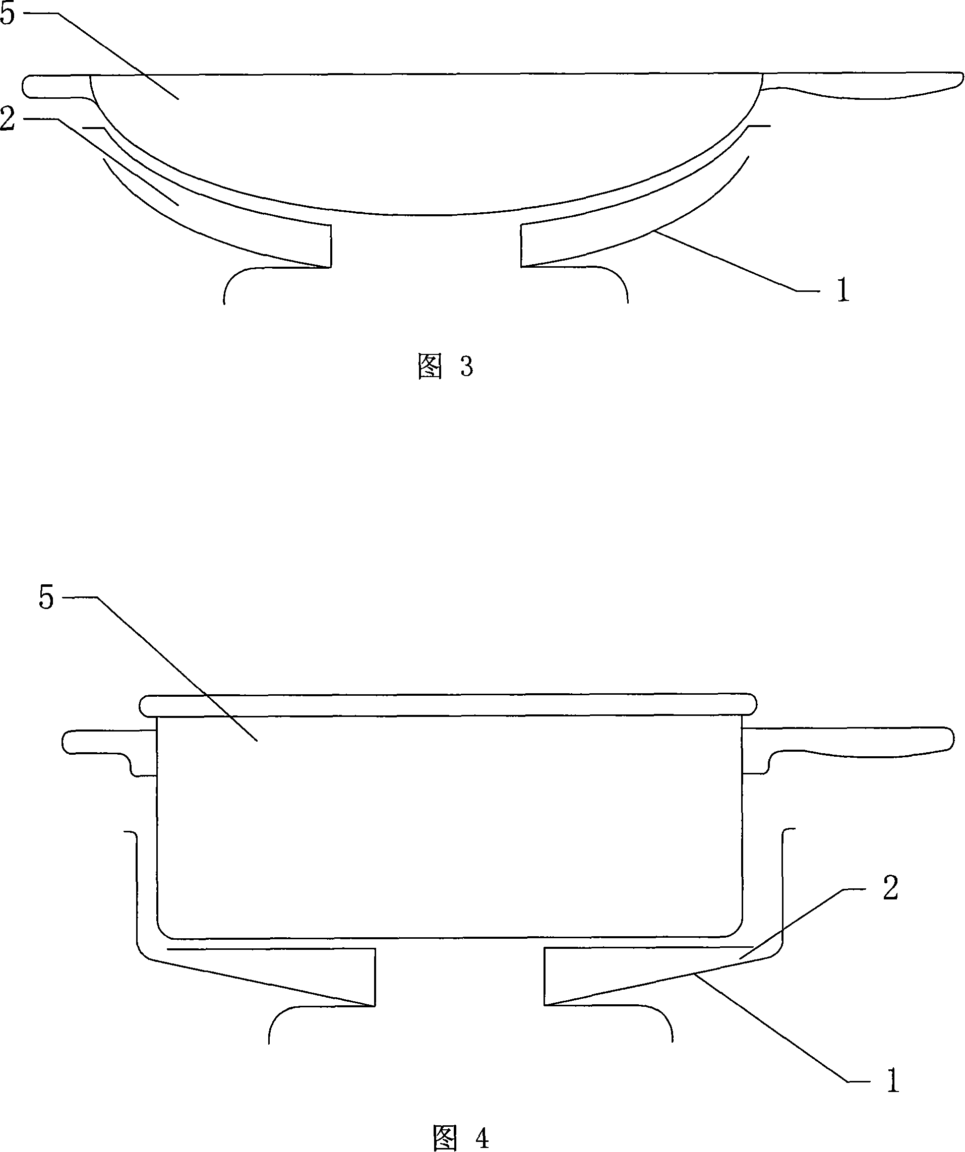
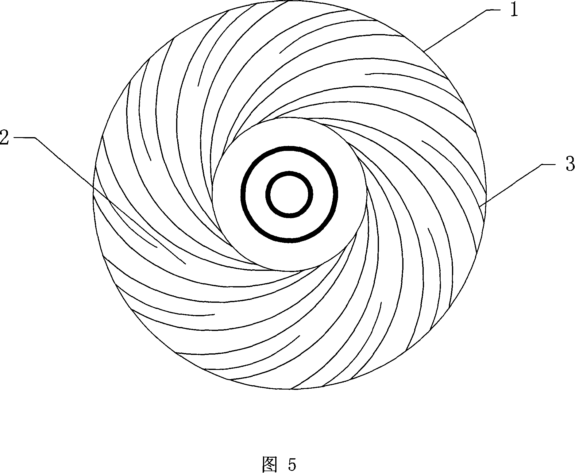
[0027] In the embodiment shown in Fig. 1, the energy-saving stove tray of the present invention includes an annular disk body 1, and the surface of the annular disk body 1 is provided with spiral grooves 2 with the same rotation direction and closely arranged, and the flame inlet of the spiral groove 2 is located in the ring The inner diameter edge of the disk body 1 and the flame outlet of the spiral groove 2 are located at the outer diameter edge of the annular disk body 1, as shown in FIG. 5 . The width of the spiral groove 2 gradually increases from the flame entrance to the flame exit, the flame exit width of the spiral groove 2 is equal to twice the flame entrance width of the spiral groove 2, and the depth of the spiral groove 2 is from the flame entrance to the flame exit Decreases gradually, the flame outlet depth of the spiral groove 2 is equal to 1 / 2 the flame inlet depth, and the phase angle difference between the flame inlet and outlet of the spiral groove 2 on the...


PUM


Abstract

The invention discloses a household single-pipe infrared furnace end, a single pipe enters from the lower side of the furnace end and is communicated with a combustion chamber; the bottom of the single pipe, a primary inclined plane faced by the single pipe and two inclined planes at both sides form an inlet cavity. The invention is characterized in that a half-round gas diversion post is arranged on the primary inclined plane of the inlet cavity, the function of the gas diversion post is to reduce the gas pressure and at the same time most of the gas is evenly divided into two parts before entering the combustion chamber; in this way, the gas is evenly mixed with the air and filled in the whole combustion chamber, and the purpose of high-temperature combustion and uniform combustion on a ceramic combustion board arranged at the top of the furnace end can be realized. The invention of the single-pipe infrared furnace end is additionally provided with a standard-sized locating clip, and can be matched and used with a standard furnace.

Description

(1) Technical field: [0001] The invention relates to a supporting part of a domestic gas stove, in particular to an energy-saving stove tray. (two) background technology: [0002] When the gas furnace is in use, the heated object such as the pot body is directly erected on the burner head with a bracket, and the flame burning on the burner head directly heats the bottom of the pot. Since the flame is exposed to the air and is open, a large amount of heat is transferred from the furnace Dissipate into the air between the head and the bottom of the pot, so that the heat energy is wasted in vain. In order to protect the heat from dissipating, the supporting bracket used in the current gas stove has a tray. The enclosure of the tray surrounds the space between the burner head and the bottom of the pot, so that the flame is concentrated in the tray and burns, which plays a certain role in preventing the heat from dissipating. role. [0003] A typical tray is represented by the ...

Claims


Application Information

Patent Timeline
Patent Type & Authority Applications(China)
IPC IPC(8): F24C15/10
Inventor 韩久和戴宗青
Owner 韩久和
Why Eureka
Try Eureka