
Automatic tracking display system for warn

A display system and automatic tracking technology, applied in the direction of alarms, anti-theft alarms, instruments, etc., can solve problems such as inability to connect to the Internet, heavy monitoring workload, and misunderstanding of police situations, reducing the number and workload, reducing engineering costs, The effect of promoting

Active Publication Date: 2008-02-20
XIAN QIYANG INFORMATION IND CO LTD
View PDF0 Cites 20 Cited by
  • Summary
  • Abstract
  • Description
  • Claims
  • Application Information

AI Technical Summary

Problems solved by technology

In this way, when the number of monitoring targets is small, the personnel on duty can also handle it freely, but when there are many monitoring targets, a lot of monitors are needed, which not only requires a lot of investment, but also it is difficult for the personnel on duty to take care of many monitor screens at the same time
The problem that this kind of monitoring system exists is that the monitoring workload is heavy, and it is not easy to realize network management in a large area (such as the whole city)
Most of the current monitoring systems that can form a network use video virtual lines of defense (such as infrared probes, etc.) to carry out alarm forecasts. Alarm signal, often causing false alarms
[0003] Both of the above two technical prevention systems have the disadvantages of misunderstanding of the police situation and the inability to connect the entire city to the network. There are technical and economic obstacles to the full realization of the security technology prevention regulations successively issued by various provinces and cities in our country.
Moreover, it is not easy to achieve a wider range of networked technical defense management, and it is impossible to track the close-up pictures of the crime scene in the first time period, which will delay the timing of the police and the arrest of the suspect.

Method used


Image

  • Automatic tracking display system for warn
  • Automatic tracking display system for warn
  • Automatic tracking display system for warn

Examples


Embodiment Construction

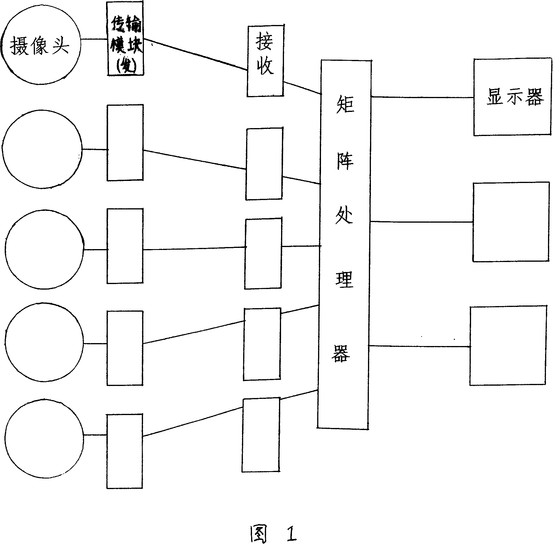
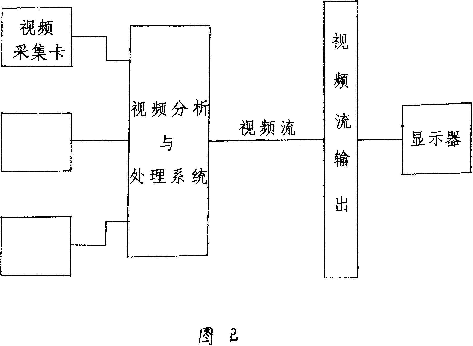
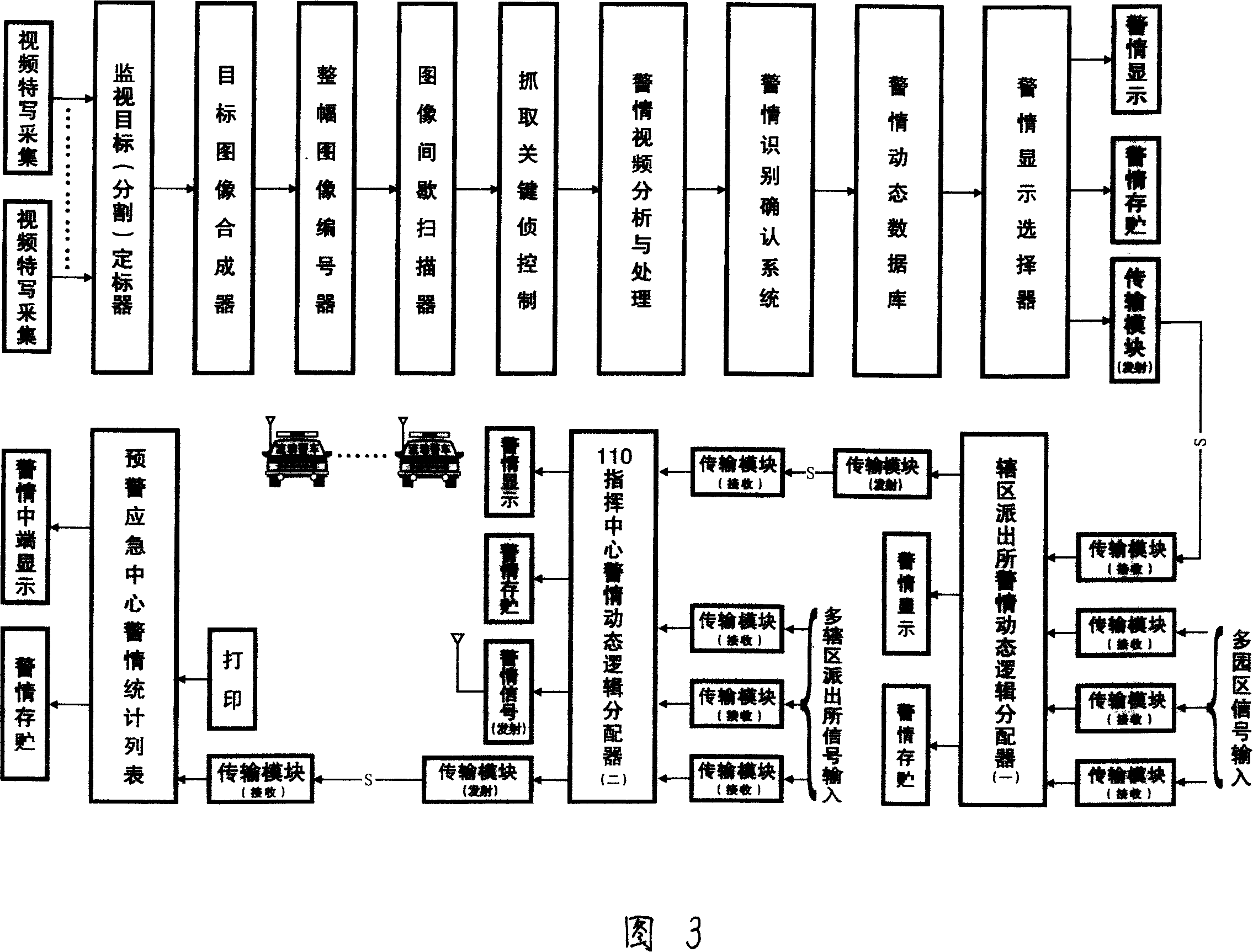
[0030] As shown in accompanying drawings 1, 2 and 3, the angle of view range of the video close-up camera installed at the monitoring target site for collecting video signals coincides with the segmentation calibration line of the monitoring target, and will collect the segmentation close-up with overlapping calibration lines After the image is synthesized by the target image synthesizer, it is encoded, and after encoding, it is synthesized by the synthesizer. After encoding, it is encoded, and after encoding, the image is intermittently scanned for 4:1 duty scanning, and the scanned image is captured for key frames. , the frame rate signal is sent to the alarm video analysis processor for processing, after processing, the alarm signal is confirmed by the alarm identification confirmation system, and the alarm signal is sent to the alarm dynamic database, and then selected by the alarm display selector The alarm signal to be displayed will be displayed and alarmed at the gate g...


PUM


Abstract

The utility model belongs to an automatic alert tracking and displaying system of signaling device, and comprises a plurality of video cameras which are arranged in observed object or place and are used for obtaining video signal, wherein the camera lens is connected with an intelligent matrix processor via a transmission module and the intelligent matrix processor can receive the video signal and can only send out a video signal when dangerous situation happens by filtering process; the intelligent matrix processor is connected with a monitor and the amount of the monitors is much less than the amount of the camera lenses; the monitor is used to display the video frame of dangerous object or place. Multi-video signals are input into the system and only the dangerous video signal can be output (pop out), therefore the amount of monitors is greatly reduced and the amount of operators on duty and the workload are both reduced, more importantly the vital time of police getting involved in is saved. The utility model can greatly save the investment of safety and protection system, avoid the negligence or any delay and ensure alarming when danger happens, therefore can be used in monitoring residence community, public place and command centers of police, and is easy to popularize the safety and protection system.

Description

technical field [0001] The invention belongs to a signal device, in particular to an automatic tracking and display system for alarm situation composed of video signals of monitoring points. Background technique [0002] Existing video surveillance systems all adopt multiple cameras to collect video signals of surveillance sites or targets, and use monitors equal in number to the surveillance cameras to observe the results. In this way, when the number of monitoring targets is small, the personnel on duty can also cope with it freely, but when there are many monitoring targets, a lot of displays are needed, which not only requires a lot of investment, but also the personnel on duty are difficult to take care of many display screens at the same time. The problem that this monitoring system exists one is that the monitoring workload is heavy, and it is not easy to realize large-scale (such as the whole city) network management. Most of the current monitoring systems that can ...

Claims


Application Information

Patent Timeline
IPC IPC(8): G08B13/196G08B25/00
Inventor 姚引良乌永陶张魁武支录奎
Owner XIAN QIYANG INFORMATION IND CO LTD
Features
  • Generate Ideas
  • Intellectual Property
  • Life Sciences
  • Materials
  • Tech Scout
  • Unparalleled Data Quality
  • Higher Quality Content
  • 60% Fewer Hallucinations
Learn More