A coupling output structure for gyrotron traveling wave amplifier

A coupling-output structure, traveling wave tube amplifier technology, applied in the microwave field, can solve the problems of insufficient stray mode suppression ability, large size, low enough reflection coefficient of input port, etc., to meet the assembly requirements of the whole tube, smooth inner wall, good Effect of stray mode suppression capability

Inactive Publication Date: 2008-02-20
INST OF ELECTRONICS CHINESE ACAD OF SCI
View PDF0 Cites 10 Cited by
  • Summary
  • Abstract
  • Description
  • Claims
  • Application Information

AI Technical Summary

Problems solved by technology

[0007] The purpose of the present invention is to solve the problems of the single-segment modified Dolf-Chebyshev tapered circular waveguide structure in the prior art, such as the size is too large, the reflection coefficient of the input port is not low enough, and the mixed mode suppression ability is not strong enough. The invention provides a coupling output structure of a gyrotron traveling wave tube amplifier

Method used


Image

  • A coupling output structure for gyrotron traveling wave amplifier
  • A coupling output structure for gyrotron traveling wave amplifier
  • A coupling output structure for gyrotron traveling wave amplifier

Examples


Embodiment 1

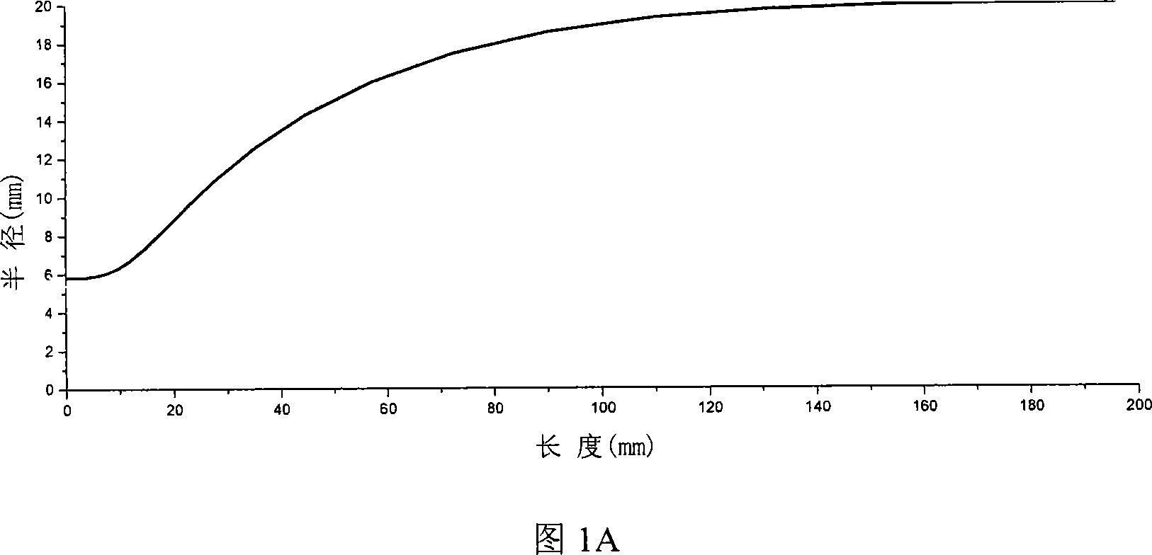
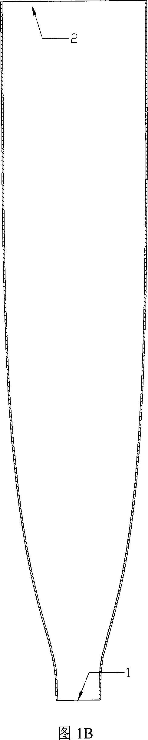
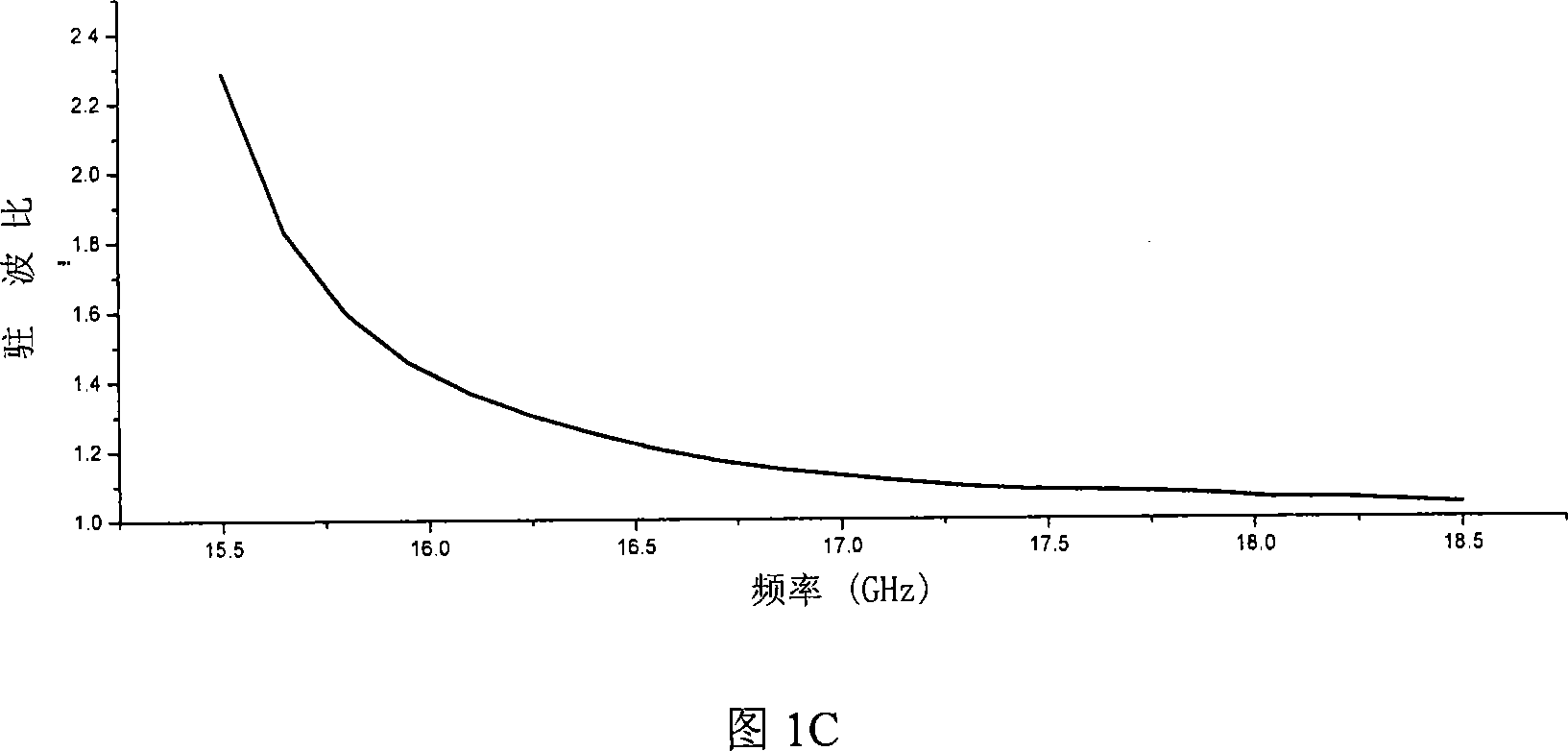
[0045] Embodiment 1: Please refer to Fig. 2A, Fig. 2B, Fig. 2C and Fig. 2D, the details of the coupling output structure of the convoluted traveling wave tube amplifier designed by cascading two sections of modified Dolf-Chebyshev tapered circular waveguides . Please refer to FIG. 2A , which shows the variation of the radius with the axial distance in Embodiment 1. Referring to FIG. In Figure 2B, the coupling output structure adopts two-stage waveguide cascading, that is, the first-stage tapered circular waveguide 3 is cascaded with the second-stage tapered circular waveguide 4; one end of the first-stage tapered circular waveguide 3 is the input port 1, and the second stage tapered circular waveguide One end of the tapered circular waveguide 4 is the output port 2 . Both the first-stage tapered circular waveguide 3 and the second-stage tapered circular waveguide 4 are modified Dolf-Chebyshev tapered circular waveguides. The design parameters of this embodiment are: the radi...

Embodiment 2

[0049] Embodiment 2: Please refer to Fig. 3A, Fig. 3B, Fig. 3C and Fig. 3D, which shows the design of two sections of modified Dolf - Chebyshev tapered circular waveguide loaded with a section of uniform circular waveguide cascaded in the middle. Details of the coupling output structure of the gyrotron traveling wave tube amplifier. Please refer to FIG. 3A , which shows the variation of the radius with the axial distance in Embodiment 2 of the present invention. In FIG. 3B, the coupling output structure adopts three-stage waveguide cascading, that is, there is a cascade connection between the first-stage tapered circular waveguide 5 and the third-stage tapered circular waveguide 7; one end of the first-stage tapered circular waveguide 5 is an input port 1. One end of the third-stage tapered circular waveguide 7 is the output port 2 . The first-stage tapered circular waveguide 5 and the third-stage tapered circular waveguide 7 are both modified Dolf-Chebyshev tapered circular ...


PUM


Abstract

The utility model has discloses a coupling output structure for traveling wave tube amplifiers, which comprises an input port and an output port; wherein, the radius of the output port is bigger than that of the input port, a first grade gradually variable circle waveguide and an Nth rank gradually variable circle waveguide are cascaded between the input port and the output port. The utility model adopts the double-segment correcting Duelfer-Chebyshev gradually variable circle waveguide cascade connection or a transition circle waveguide cascaded in the central section of the double-segment correcting duelfer-chebyshev gradually variable circle waveguide. The utility model has the advantages of resolving the problems in prior art , such as large size, high reflection coefficient of the input port and weak capacity of parasitic mode restraint; when the coupling output structure is applied to traveling wave tube amplifiers, positive effects can be obtained, , which are of great practical significance for developing the high power microwave sources applied in long ranged radars and electronic warfare technology.

Description

technical field [0001] The invention belongs to the field of microwave technology, and particularly relates to high-power microwave devices. Background technique [0002] There is a big gap between my country and foreign countries in the development of long-range radar, mainly because there is no suitable high-power microwave source, and the power of the high-power microwave source developed in China is far from meeting the needs of ultra-long-range radar systems. Amplifiers are one of the high power microwave sources most likely to meet this requirement. [0003] Fundamentally speaking, the coupling output structure of the gyrotron amplifier is a circular waveguide gradient structure, and its main function is to match the circular waveguide with a smaller radius to the circular waveguide with a larger radius. There are many gradient methods for the gradient structure that can accomplish this function, such as linear gradients, exponential gradients, and Chebyshev gradients....

Claims


Application Information

Patent Timeline
Patent Type & Authority Applications(China)
IPC IPC(8): H01P5/08H01P5/00
Inventor 杜朝海刘濮鲲耿志辉
Owner INST OF ELECTRONICS CHINESE ACAD OF SCI
Why Eureka
Try Eureka