Monitoring device for online continuous welding area

A monitoring device, welding area technology, applied in auxiliary devices, welding equipment, auxiliary welding equipment and other directions, can solve the problems of limited resolution, high labor intensity, welding torch adjustment, etc., achieve high resolution, reduce labor intensity, improve quality effect

Inactive Publication Date: 2008-02-20
江苏薪泽奇机械股份有限公司
View PDF0 Cites 10 Cited by
  • Summary
  • Abstract
  • Description
  • Claims
  • Application Information

AI Technical Summary

Problems solved by technology

Due to the limited resolution of the human naked eye, it is impossible to observe subtle changes in the welding area, and it is impossible to adjust the welding torch in time, thereby affecting the quality of the product; moreover, the observer maintains a posture for a long time, which is labor-intensive. It is easy to cause fatigue and inattention, so that many abnormal conditions in the welding area are not captured, so the welding torch is not adjusted in time, which affects the quality of the product

Method used


Image

  • Monitoring device for online continuous welding area

Examples


Embodiment Construction

[0011] Specific embodiments of the present invention will be described in detail below in conjunction with the accompanying drawings.

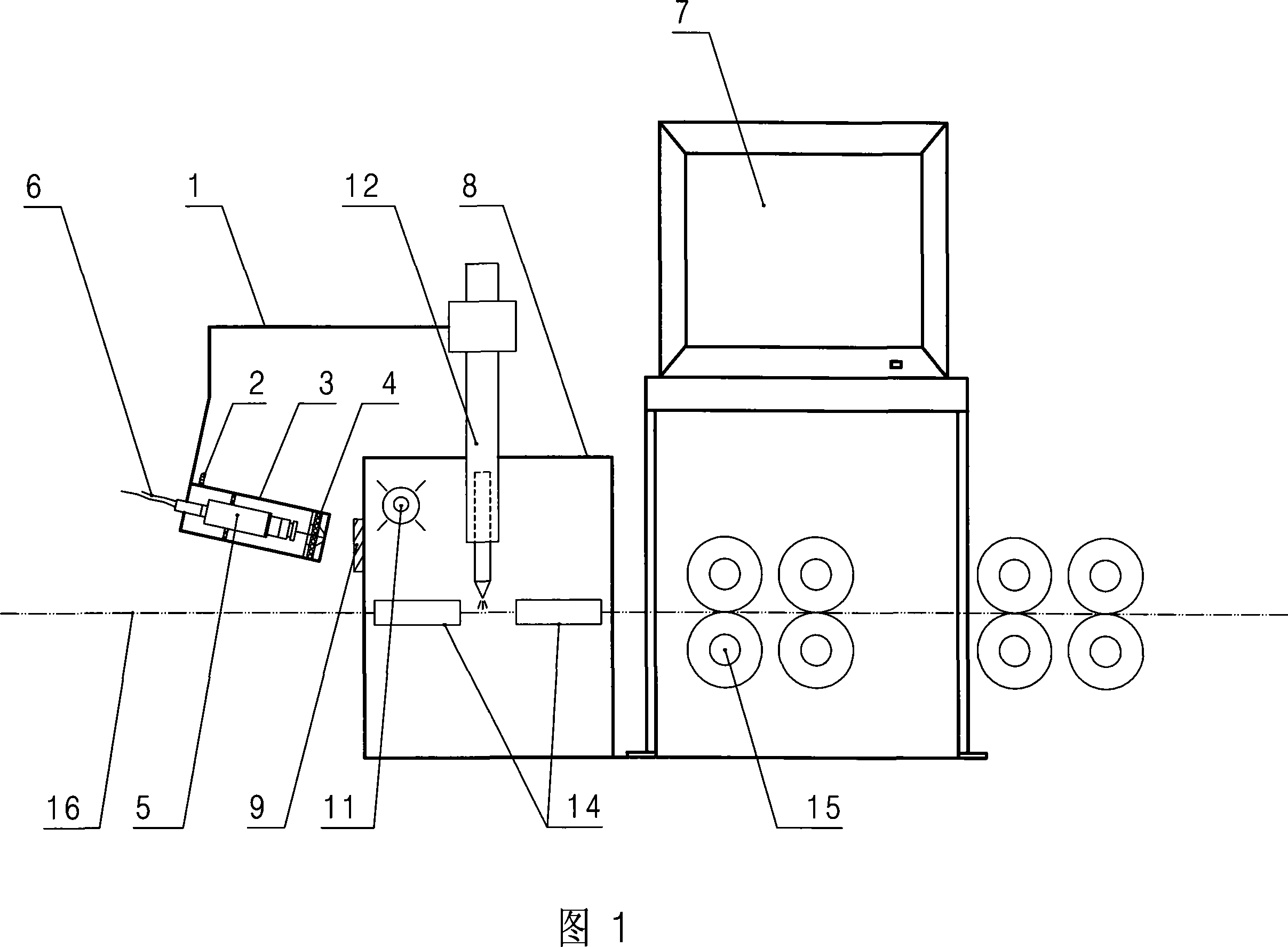
[0012] As shown in Figure 1, the monitoring device of the on-line continuous welding zone of the present invention comprises: the observation window 9 that is arranged on the welding protective cover 8, and the color camera 5 is arranged on the installation frame 1, and the camera lens of color camera 5 faces Observation window 9, before the lens of color camera 5 is provided with the optical filter lens 4 that is used to filter out the glare that welding produces, the output signal of color camera 5 is connected with the input end of color display 7 by signal output line 6. In this embodiment, the color camera 5 and the optical filter lens 4 are arranged in the protective tube 3 provided with the air inlet 2, and the end wall of the protective tube 3 is provided with a peephole corresponding to the optical filter lens 4, The protective tube 3...


PUM


Abstract

The utility model discloses a monitoring device for on-line continuous welding zone which automatically observes slight changes of the welding zone in order to reduce the labor intensity and enhance the product quality. The utility model comprises an observation window positioned at a welding protection cover, a colorful video camera arranged opposite to the observation window, an optical filtering lens arranged in front of the colorful video camera and a colorful display which is used to display the output signals of the colorful video camera. The utility model is mainly applied to observe the welding zone during the edge joint of welding metal pipes.

Description

technical field [0001] The invention relates to a monitoring device for observing the welding condition of the welding zone during the jointing process of welding metal pipes. Background technique [0002] As everyone knows, most metal pipes are formed by welding the seams between the welding extrusion rollers after the metal plates are crimped and formed by the driving rollers. In order to clearly observe the welding condition of the welding area, observers generally observe through a protective cover provided with a color filter observation window. Due to the limited resolution of the human naked eye, it is impossible to observe subtle changes in the welding area, and it is impossible to adjust the welding torch in time, thereby affecting the quality of the product; moreover, the observer maintains a posture for a long time, which is labor-intensive. It is easy to cause fatigue and inattention, so that many abnormal conditions in the welding area are not captured, so the ...

Claims


Application Information

Patent Timeline
Patent Type & Authority Applications(China)
IPC IPC(8): H04N7/18B23K37/00
Inventor 杨光耀胡清林高峰
Owner 江苏薪泽奇机械股份有限公司
Why Eureka
Try Eureka