Drawing device and its contraposition method

A technology for detecting devices and relative positions, which is applied in the direction of photolithography exposure devices, microlithography exposure equipment, etc., and can solve problems such as offsets

Inactive Publication Date: 2011-04-20
DAINIPPON SCREEN MTG CO LTD
View PDF2 Cites 0 Cited by
  • Summary
  • Abstract
  • Description
  • Claims
  • Application Information

AI Technical Summary

Problems solved by technology

However, in the above conventional method, the drawing position of the optical head is determined only based on the alignment marks formed at the four corners of the substrate.
Therefore, in all exposed areas, the pattern may not be drawn at the most suitable position, and in some exposed areas, there may be a shift between the black matrix and the drawn pattern

Method used


Image

  • Drawing device and its contraposition method
  • Drawing device and its contraposition method
  • Drawing device and its contraposition method

Examples


no. 1 approach

[0096] Next, a first embodiment of the present invention will be described with reference to the drawings. In addition, in each drawing referred to in the following description, a common XYZ rectangular coordinate system is used in order to clarify the positional relationship and operation direction of each member.

[0097]

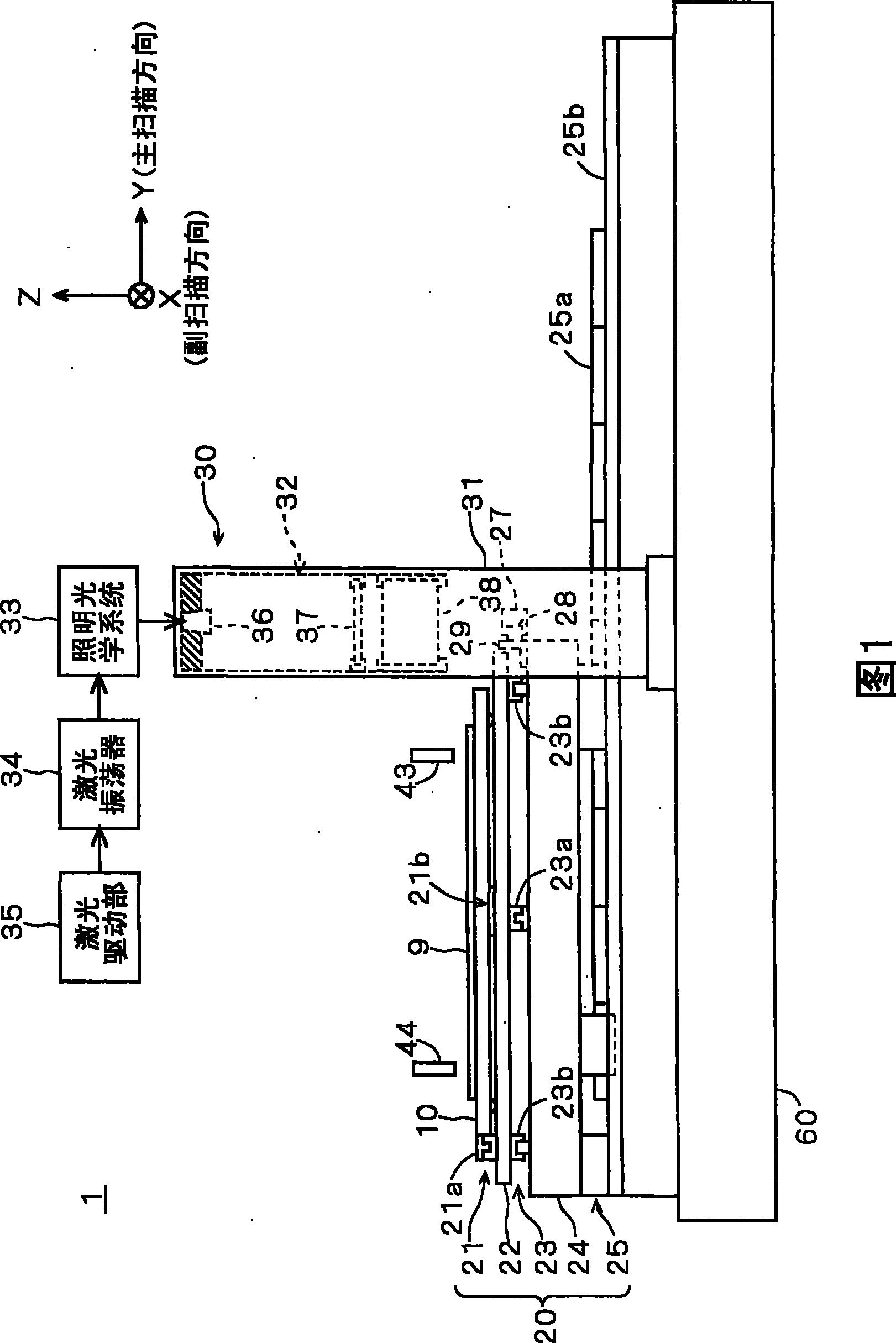
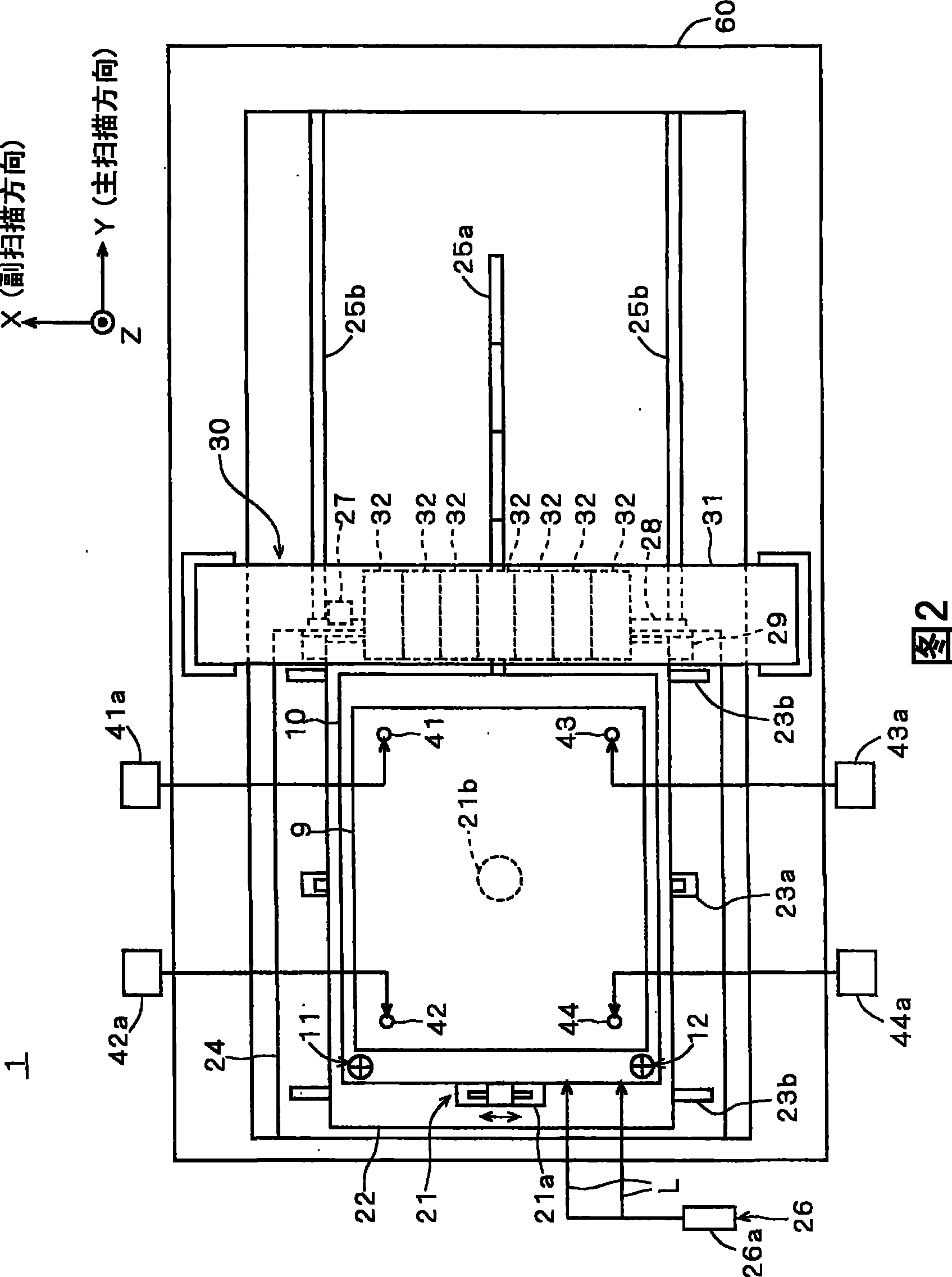
[0098] 1 and 2 are side views and plan views showing the configuration of a pattern drawing device 1 according to a first embodiment of the present invention. The pattern drawing device 1 is a device for drawing a predetermined pattern on the upper surface of a glass substrate for color filter (hereinafter simply referred to as "substrate") 9 in a process of manufacturing a color filter of a liquid crystal display device. As shown in FIGS. 1 and 2 , the pattern drawing device 1 includes a workbench 10 for holding a substrate 9, a drive unit 20 connected to the workbench 10, a head 30 with a plurality of optical heads 32, and a plurality of aligners. Ca...

no. 2 approach

[0161] Next, a second embodiment of the present invention will be described with reference to the drawings. The pattern drawing device 101 of the second embodiment has the same configuration as the pattern drawing device 1 of the above-mentioned first embodiment, and is a device that performs the same calibration processing and drawing processing. Furthermore, in addition to the structure of the pattern drawing device 1 of the first embodiment, the pattern drawing device 101 of the second embodiment has the following structure, and in addition to the operation of the pattern drawing device 1 of the first embodiment , also perform the actions described below. In addition, in each drawing referred to in the following description, in order to clarify the positional relationship and operation direction of each member, a common XYZ rectangular coordinate system is used.

[0162]

[0163] 23 and 24 are side views and plan views showing the configuration of the pattern drawing dev...


PUM


Abstract

The present invention provides a pattern portraying device which can do portraying according to the correct position on the substrate when the no high performance activating device is used for the contraposition camera and the position relationship between a light illuminating part and the positioning camera has changed and the contraposition method. The pattern portraying device (1) detects the offset of each contraposition camera (41 to 44) relative to the relative position of the pulse light irradiated from the optical head (32), and modifies the contraposition quantity of the substrate (9) and the portraying starting position of the substrate (9) according to the offset. Thereby, the device can do portraying treatment while the device modifies the variable quantity even if the position relationship between the pulse light irradiated from the optical head (32) and each contraposition camera (41 to 44) has changed. Therefore, the pattern portraying device (1) can do portraying at correct position on the substrate (9).

Description

technical field [0001] The present invention relates to a rule for drawing on a photosensitive material formed on a substrate for a color filter included in a liquid crystal display device, a glass substrate for a flat panel display (FPD) such as a liquid crystal display device or a plasma display device, a semiconductor substrate, and a printed circuit board. A pattern drawing device, a positioning method for a substrate in the drawing device, a drawing method, and a substrate processing system. Background technique [0002] Conventionally, in the manufacturing process of a substrate, a pattern drawing device that draws a predetermined pattern on the surface of the substrate by irradiating light onto a photosensitive material formed on the surface of the substrate has been used. A conventional pattern drawing device has a stage that moves the substrate while maintaining the substrate in a horizontal posture, and an optical head that irradiates light of a predetermined patte...

Claims


Application Information

Patent Timeline
Patent Type & Authority Patents(China)
IPC IPC(8): G03F7/20
Inventor 谷口慎也和田康之林秀树小八木康幸
Owner DAINIPPON SCREEN MTG CO LTD
Why Eureka
Try Eureka