Coating device

A coating device and nozzle technology, which can be applied to devices for coating liquid on surfaces, coatings, and photolithographic process coating equipment, etc. The effect of preventing the resonance state

Inactive Publication Date: 2008-03-05
TOKYO OHKA KOGYO CO LTD +1
View PDF1 Cites 0 Cited by
  • Summary
  • Abstract
  • Description
  • Claims
  • Application Information

AI Technical Summary

Problems solved by technology

At this time, if the natural frequency of the coating device coincides with the vibration frequency of the external vibration transmitted from the ground, etc., the coating device will be in a resonant state, causing the stage and the slit nozzle to vibrate, thereby making the coating film uneven film thickness

Method used


Image

  • Coating device
  • Coating device

Examples


Embodiment Construction

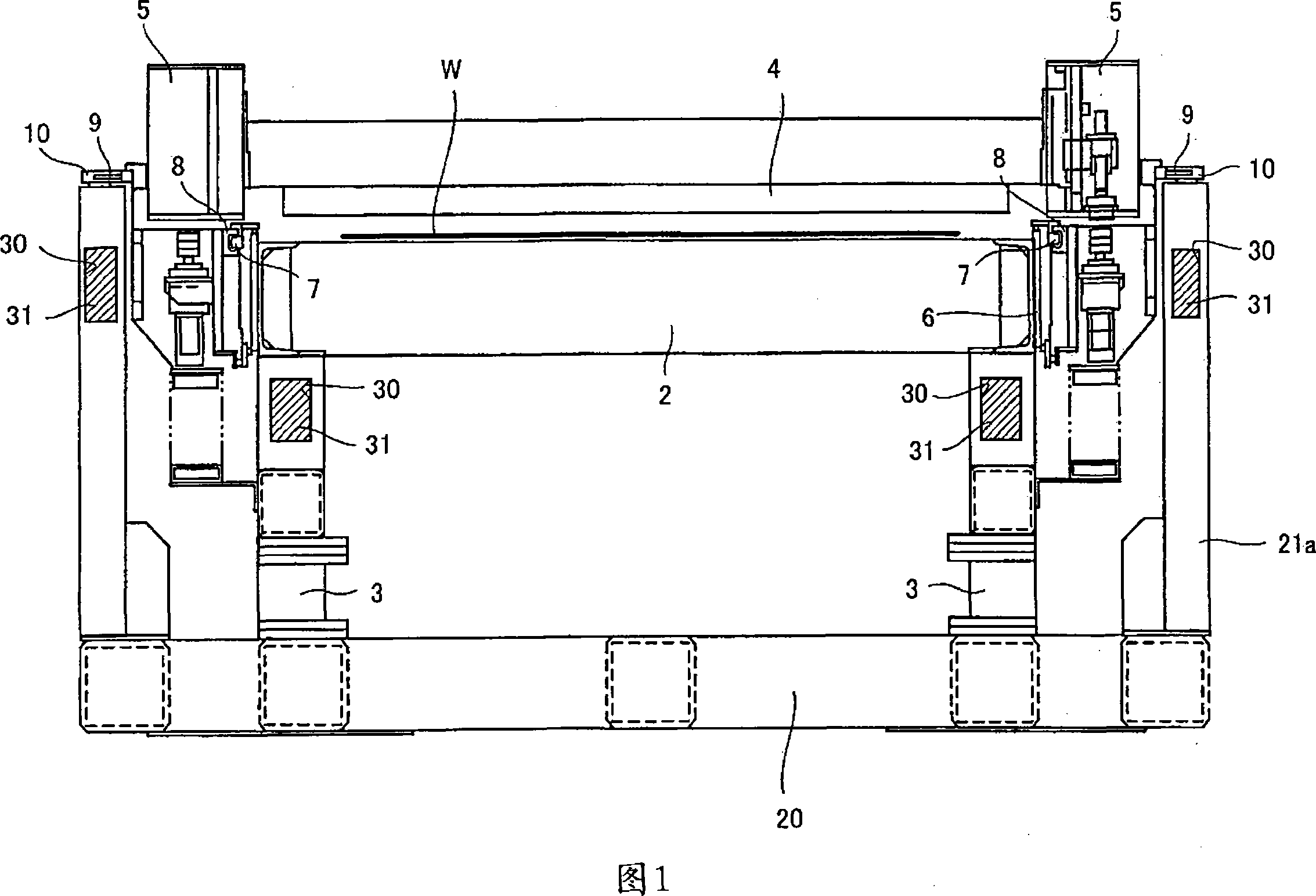
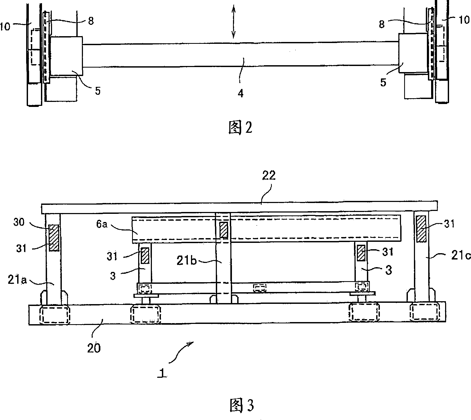
[0015] The present invention will be described in detail below with reference to the accompanying drawings. 1 to 3 show an example of a coating device of the present invention. FIG. 1 is a front view seen from the moving direction of the slit nozzle, FIG. 2 is a plan view showing the main part of FIG. 1 , and FIG. 3 is a side view showing the arrangement structure of the base frame.

[0016] The coating apparatus of the present invention has a base 1 composed of a plurality of hollow frames extending horizontally and vertically, and supports a stage 2 and a nozzle moving mechanism (moving body) by these hollow frames.

[0017] The stage 2 on which the substrate W to be processed is placed is fixed on the susceptor 1 via the pedestal 3 . A slit nozzle 4 is disposed above the stage 2. The slit nozzle 4 has a slit opening extending in the left-right direction of FIG. 1 . vertical direction) to apply the coating liquid onto the substrate W.

[0018] Both ends of the slit nozzle...


PUM


Abstract

The invention provides a coating device for weakening the influence of external vibration, in particular for inhibitting resonance caused by external vibration effectively. An anti-resonance portion (31) is filled in a suppoting carrier (2) and a cove (30) of square pipes (20, 21a-21c) of a slit nozzle travel mechanism. Beacuse filling the anti-resonance portion in square pipes can change the natural vibration frequency of a base (1), a resonance state can not be got because of external vibration.

Description

technical field [0001] The present invention relates to a coating apparatus for forming various coating films such as resist films on various substrates such as semiconductor wafers and glass substrates. Background technique [0002] A slit coater is known that uses a slit nozzle to form various coating films such as resist films on various substrates such as semiconductor wafers and glass substrates (see, for example, Patent Document 1). In the slit coater, the substrate is held on the stage by vacuum suction, and the slit nozzle is moved horizontally by the nozzle moving mechanism to form a coating film with a predetermined film thickness on the surface of the substrate. When using this slit coater to form a coating film, a predetermined distance is maintained between the substrate surface and the front end of the slit nozzle, and a predetermined amount of coating liquid is supplied while moving, and the slit is formed at a constant speed. The nozzle moves in the horizont...

Claims


Application Information

Patent Timeline
Patent Type & Authority Applications(China)
IPC IPC(8): B05C5/00B05C11/00
CPCB05C5/02G03F7/16H01L21/56
Inventor 宫本英典升芳明池尻浩一曽根康博
Owner TOKYO OHKA KOGYO CO LTD
Why Eureka
Try Eureka