Silk screen printing device and printing method thereof

A technology of screen printing device and mask, which is applied in the direction of screen printing machine, printing device, printing, etc., can solve the problems of large-scale devices, time-consuming, and large chambers.

Inactive Publication Date: 2008-03-05
HITACHI LTD
View PDF2 Cites 11 Cited by
  • Summary
  • Abstract
  • Description
  • Claims
  • Application Information

AI Technical Summary

Problems solved by technology

[0007] In this way, if the chamber is pressurized to print the paste on the printed wiring board, the chamber will float up due to the pressurized pressure, and it may be difficult to obtain the effect of pressurization.
Again, it is necessary to make the chamber very large
In addition, when the printed printed wiring board passes through the chamber too much, the paste inserted on purpose will float up, and voids may also be generated.
[0008] In addition, as in Patent Document 2, if a printing device is installed in a vacuum chamber, and the paste is degassed before printing in a vacuum state, although high-precision printing can be carried out, it is also difficult to carry in and out the printed matter. It is time-consuming, and at the same time, it takes time to vacuum the inside of the vacuum chamber, and there is also a problem of increasing the size of the device.

Method used


Image

  • Silk screen printing device and printing method thereof
  • Silk screen printing device and printing method thereof
  • Silk screen printing device and printing method thereof

Examples


Embodiment Construction

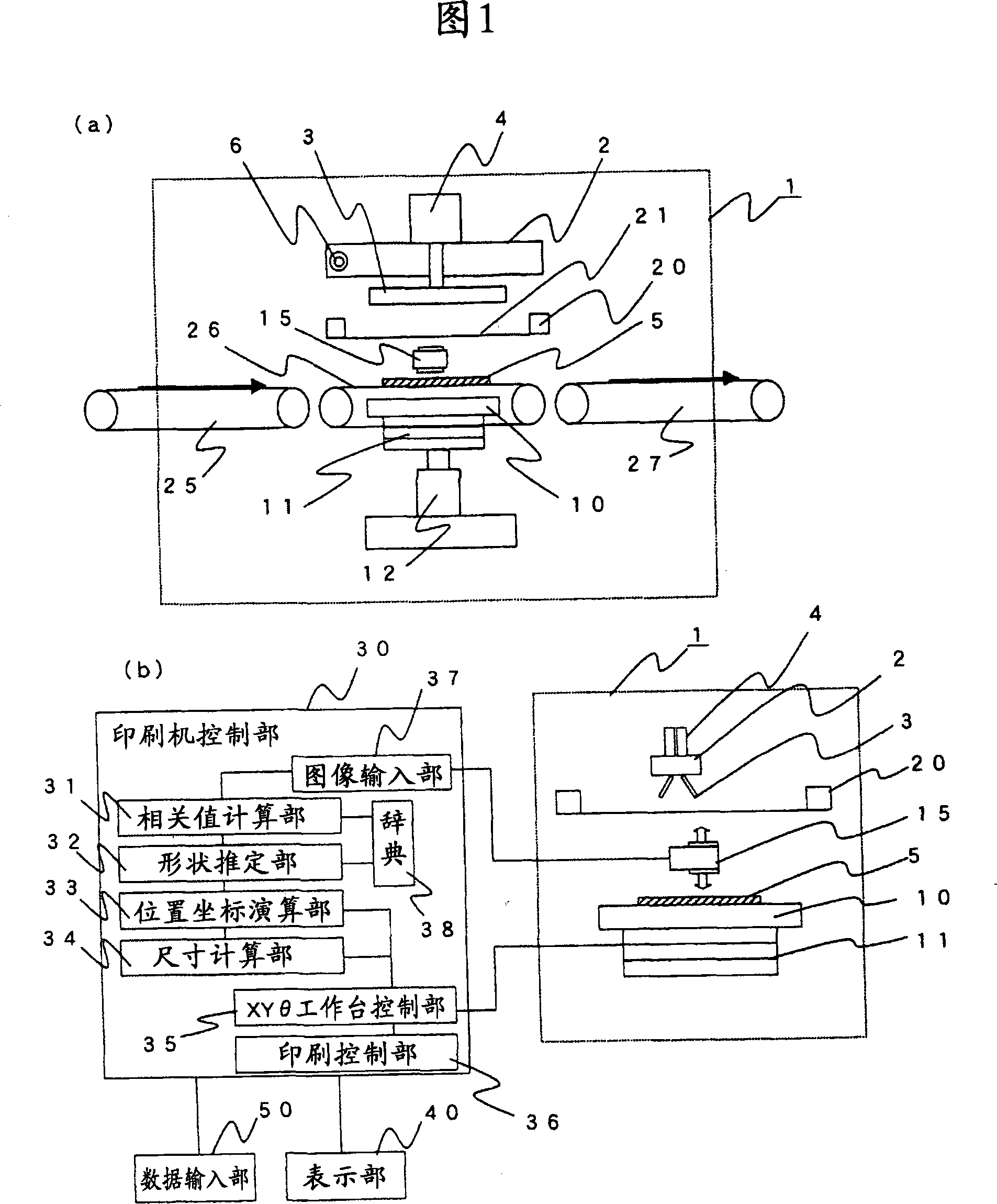
[0018] FIG. 1 shows the outline of the overall configuration of the screen printing device.

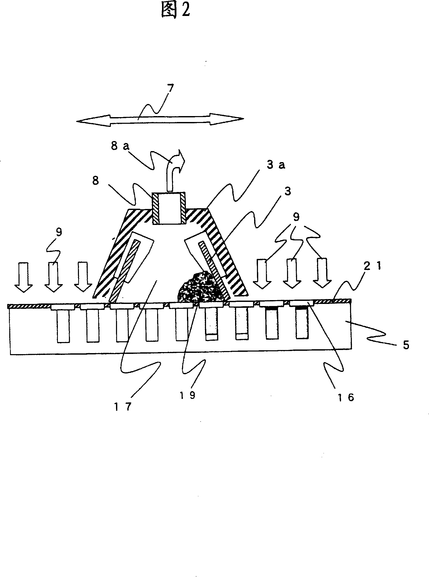
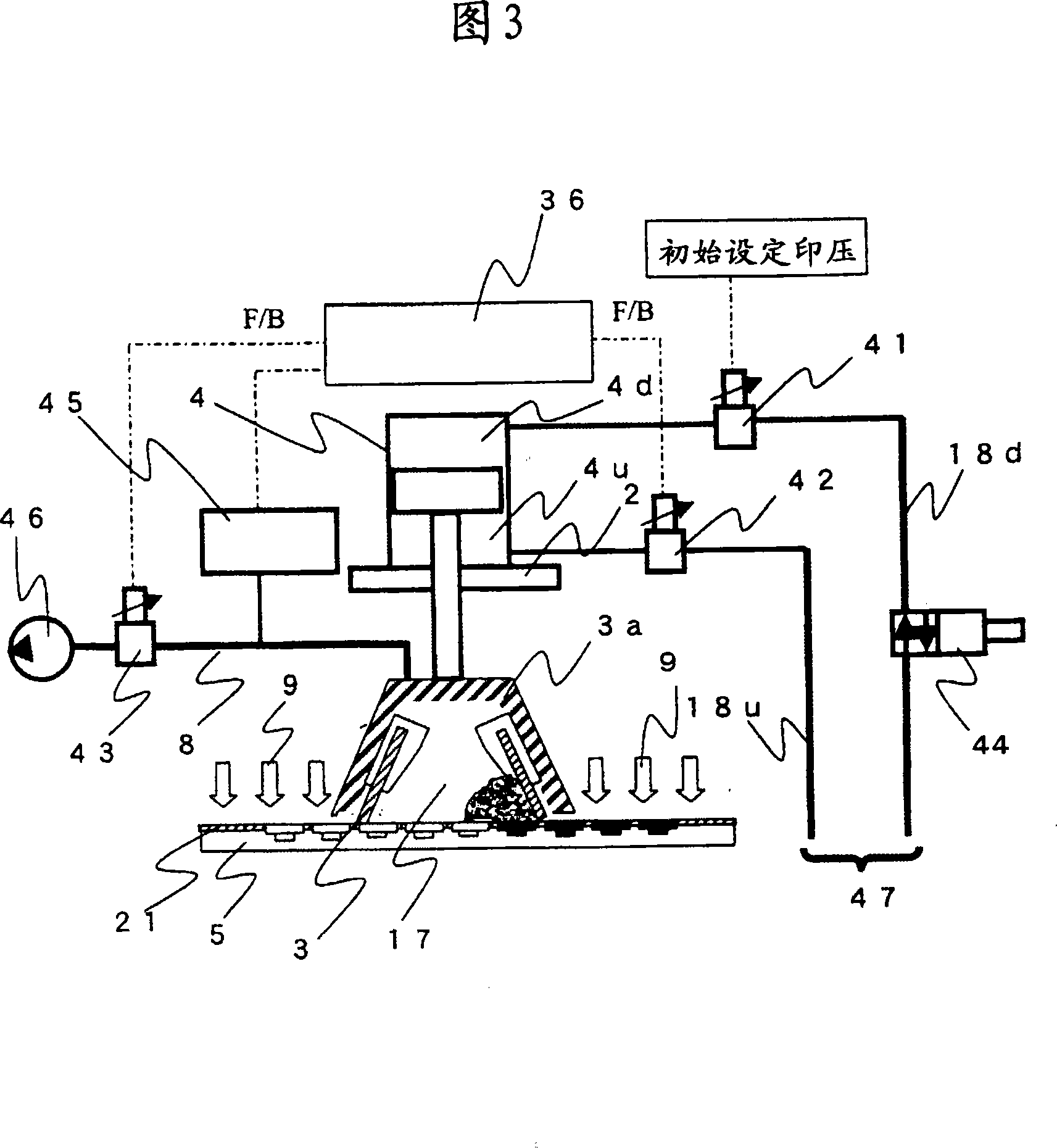
[0019] On the main body frame of the screen printing machine 1 of the present invention, a plate frame support member not shown in the figure is set, and a mask 20 with a screen 21 hanging on it is set on the plate frame support member (including the screen screen below, and also with the mask In the case of the mold being described together), the screen 21 has a printed pattern as an opening. A squeegee head 2 is arranged above the mask 20 , and a squeegee 3 is attached to the squeegee head 2 . The squeegee head 2 can move in the horizontal direction through the squeegee moving mechanism 6 , and the squeegee 3 can move in the up and down direction through the squeegee lifting mechanism 4 . In this embodiment, an example in which an air cylinder is used for the doctor blade lifting mechanism 4 is shown (hereinafter, the doctor blade lifting mechanism may simply be referred to as an a...


PUM


Abstract

The invention solves the technology problems that a printing device using a screen mask can not print with good precision when the printing objects need to be fine. In the invention, a squeegee blade head of a screen opening portion which is supplied with paste is a closed squeegee blade head, when printing, the interior of the squeegee blade head is in a negative pressure state, arranging a control mechanism makes the stamping pressure related to the squeegee blade head at a proper value through the negative pressure and printing, thereby preventing macro-scale of the device for printing with high precision.

Description

technical field [0001] The present invention relates to a screen printing device, in particular to a screen printing device having a fillable filling head in an opening with a high aspect ratio and a printing method thereof. Background technique [0002] Conventionally, Patent Document 1 discloses a solder printing device capable of simply and reliably printing solder on a stencil such as a stencil having small-diameter holes corresponding to small wiring patterns. Solder paste (hereinafter referred to as paste). In Patent Document 1, a control unit controls the operation of a pressurizing unit that applies pressure to the paste applied to the stencil and the operation of a stencil drive unit that drives the stencil. [0003] In addition, Patent Document 2 discloses a situation in which the entire printing device is installed in a vacuum chamber, a coating process and a printing process are provided, and a defoaming process is provided before the printing process after the ...

Claims


Application Information

Patent Timeline
Patent Type & Authority Applications(China)
IPC IPC(8): B41F15/46B41F15/42B41M1/12H05K3/12H05K3/34
CPCB41F15/14B41F15/423B41F15/44
Inventor 川边伸一郎向井范昭五十岚章雄和田正文
Owner HITACHI LTD
Why Eureka
Try Eureka