
Kinetic energy apparatus

A kinetic energy and buoy technology, applied in engine components, machines/engines, hydropower, etc., can solve problems such as unavailability, reduction in power generation, and inability to store 100% of kinetic energy power generation.

Inactive Publication Date: 2008-03-05
童瑞祺
View PDF0 Cites 7 Cited by
  • Summary
  • Abstract
  • Description
  • Claims
  • Application Information

AI Technical Summary

Problems solved by technology

This kind of conventional technology must consume energy to run the air compressor to compress the air before generating electricity. Part of the energy consumed is used to drive the air compressor, so the power generation will be reduced, and the kinetic energy or power generated cannot be stored 100%
[0005] Known devices that use buoyancy to generate kinetic energy to generate electricity must consume energy before generating electricity in order to drive the air compressor to compress the air and supply the compressed air required by the buoyancy equipment. Therefore, energy must be consumed after generating electricity. Part of the energy is used to drive the air compressor, so the power generation will be reduced, and the kinetic energy or power generation cannot be stored 100%; in addition, in the absence of any energy supply, the conventional buoyancy power generation device will not be able to use

Method used


Image

  • Kinetic energy apparatus
  • Kinetic energy apparatus
  • Kinetic energy apparatus

Examples


Embodiment Construction

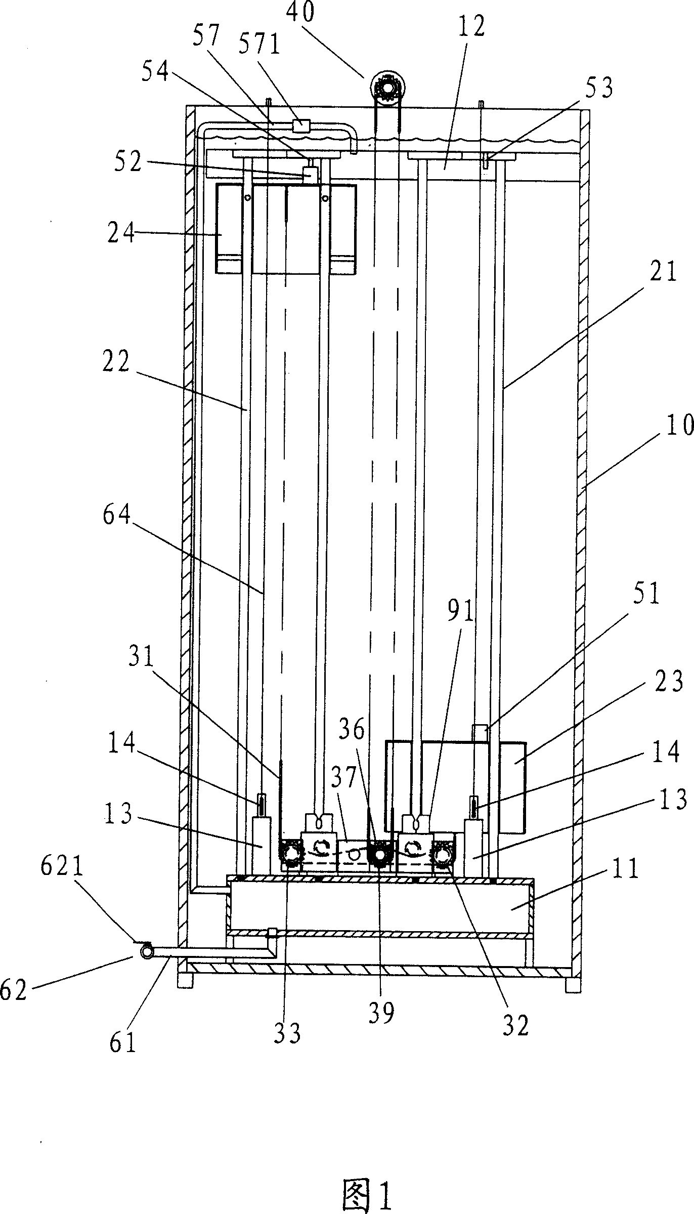
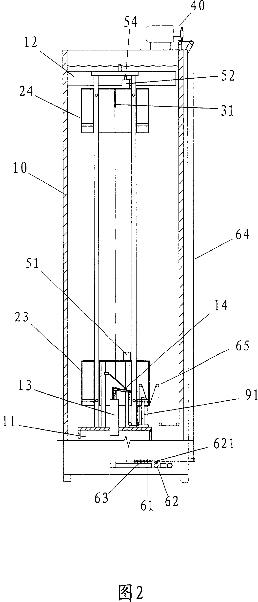
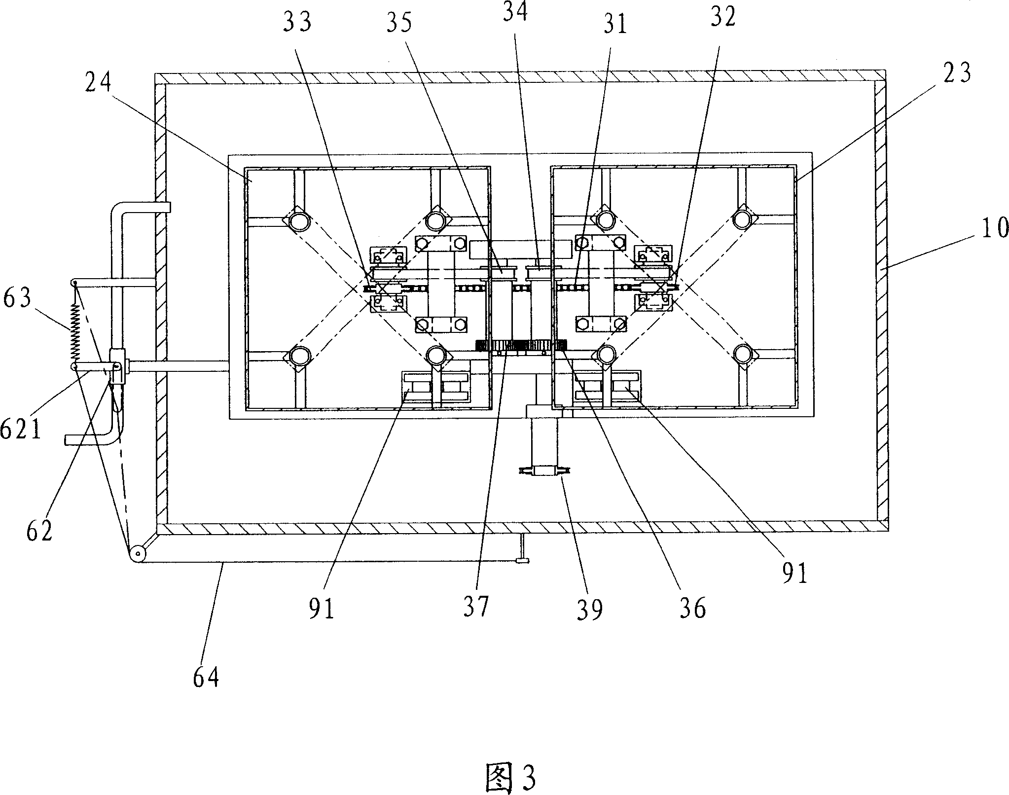
[0037] Please refer to shown in Fig. 1, 2, 3, the hydraulic type kinetic energy device of the present invention mainly comprises a water tank 10, and an air storage tank 11 is arranged at the bottom of the water tank 10, and a slide is arranged between the gas storage tank 11 and the air storage cover 12 at the top. Column group 21,22, is accommodated for two buoys 23,24, is connected with chain 31 between two buoys 23,24 and goes around two sprockets 32,33 on the gas storage tank 11, and two sprockets 32,33 are provided with One-way bearings, and the one-way bearings of the two sprockets 32,33 are arranged in reverse, so that the chain 31 can only drive the rotation of a single sprocket when sliding up and down; 321 , 331 drive two mutually meshing gears 36 , 37 with pulley sets 34 , 35 , one gear 36 is connected to an output shaft 38 , and the sprocket 39 of the output shaft 38 is linked to the generator set 40 .

[0038] The tops of the aforementioned buoys 23, 24 are provi...


PUM


Abstract

In the slide column group in the water trough are set with two floating tubes that one is at upper part and the other is lower and the two floating tubes are connected by a chain. The extrusion air in the air-accumulation tube at the bottom part of the water trough is charged into the floating tube at most lower part of the water trough by the power of water pressure in the water trough, the water in the floating tube is extruded by the air and discharged out. The top one-way air valve of the upper floating tube is pushed open by a contact-press tube to form open circuit state to make the air in the floating tube flow into the top air-accumulation cover, so the floating tube is filled up gradually to generate gravity. The two floating tubes act alternatively one upper and one down. Advantages: it is a kinetic energy device with minimum water discharge amount.

Description

technical field [0001] The present invention relates to a power generation device, in particular to a kinetic energy device that utilizes the interaction of water pressure and air buoyancy to generate kinetic energy of a power generation device and minimizes the amount of discharged water. Background technique [0002] Commonly used power generation equipment, such as hydroelectric power generation equipment, uses a reservoir formed by a fence to generate electricity. The kinetic energy generated by the change of water level is used to drive the power generation equipment to rotate to generate electricity. Therefore, the kinetic energy generated by a water level change can only be used to generate electricity. For power generation, although the power company can pump the discharged water back for use, it is carried out during peak power consumption hours, and it must sacrifice electric energy to pump back the outflowed water. This is the shortcoming of general reservoir-type ...

Claims


Application Information

Patent Timeline
Patent Type & Authority Applications(China)
IPC IPC(8): F03B17/02
CPCY02E10/20
Inventor 童瑞祺
Owner 童瑞祺
Learn More