System and method for cooling a bog stream

A gas flow and refrigeration system technology, applied in the direction of refrigeration and liquefaction, liquefaction, cold treatment separation, etc., can solve the problem of large temperature difference in the middle

Inactive Publication Date: 2008-03-05
海威KSE气体系统公司
View PDF2 Cites 12 Cited by
  • Summary
  • Abstract
  • Description
  • Claims
  • Application Information

AI Technical Summary

Problems solved by technology

Compander complexity is minimized using only one stage expander, but the intermediate temperature difference between the hot and cold streams is unduly large in the middle of the cold box

Method used


Image

  • System and method for cooling a bog stream
  • System and method for cooling a bog stream
  • System and method for cooling a bog stream

Examples


Embodiment Construction

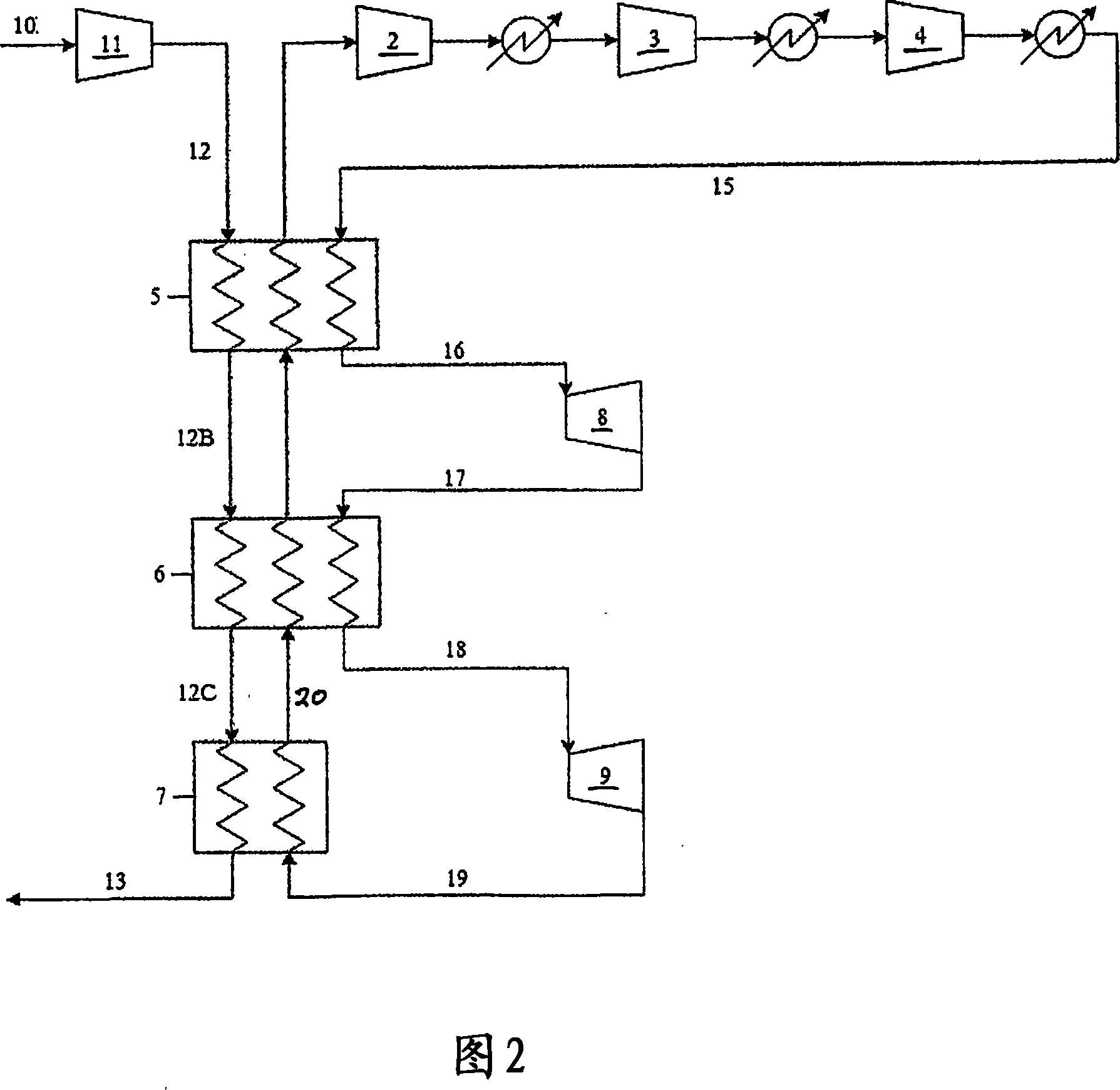
[0028] Implementing two expanders 8, 9 connected in series instead of parallel expanders can reduce the thermodynamic emissivity without splitting air flow Loss. A closed coolant (nitrogen) cycle would be similar to FIG. 2 , with boil-off gas from a storage tank (not shown) entering compressor 11 through line 10 . The compressed air stream 12 is sent through heat exchangers 5, 6, 7 and exchanges heat against a closed loop refrigeration system (the arrangement is commonly referred to as a "cold box"). While the cold box is being carefully adjusted, the stream 13 from the heat exchanger should be fully reliquefied.

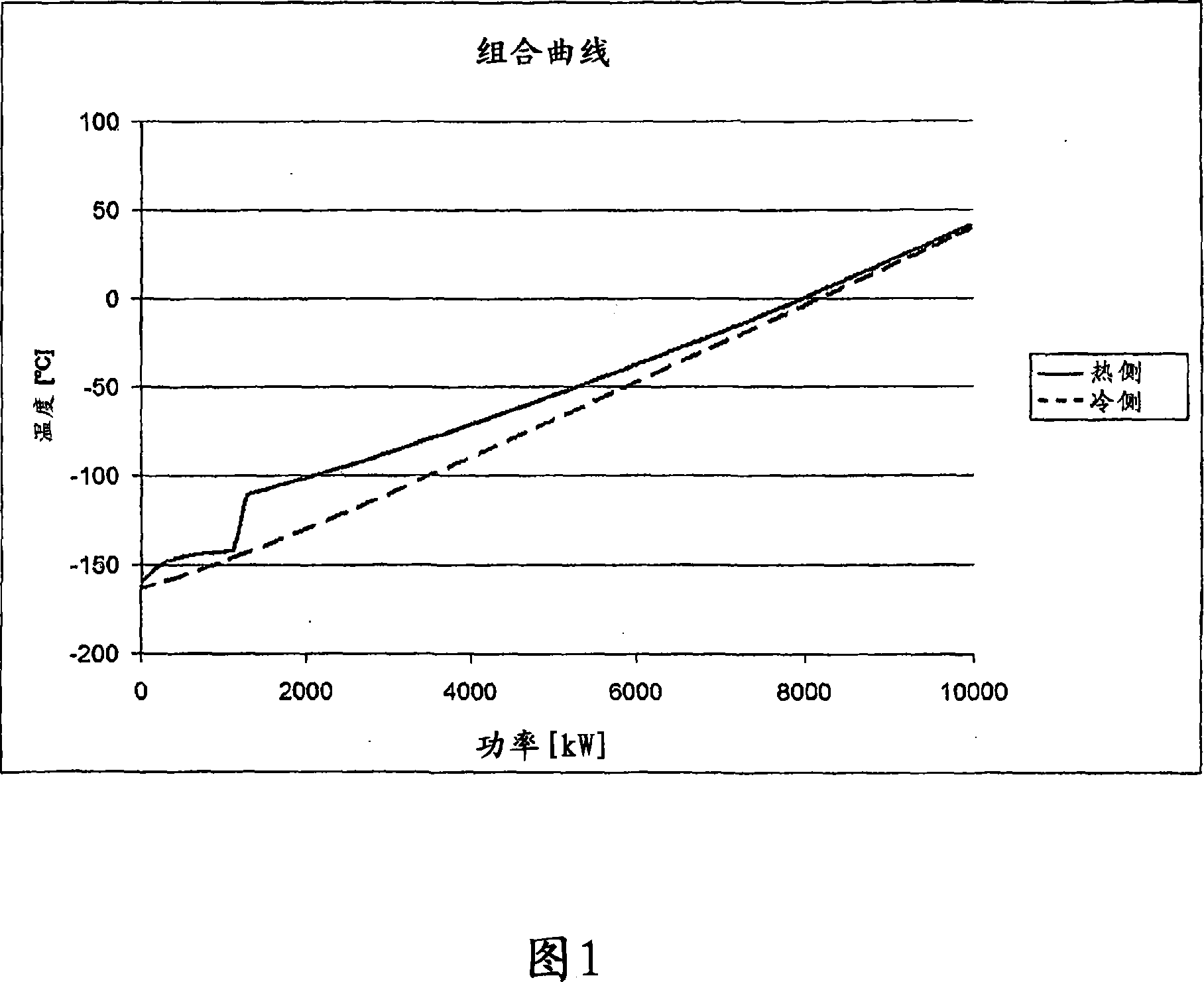
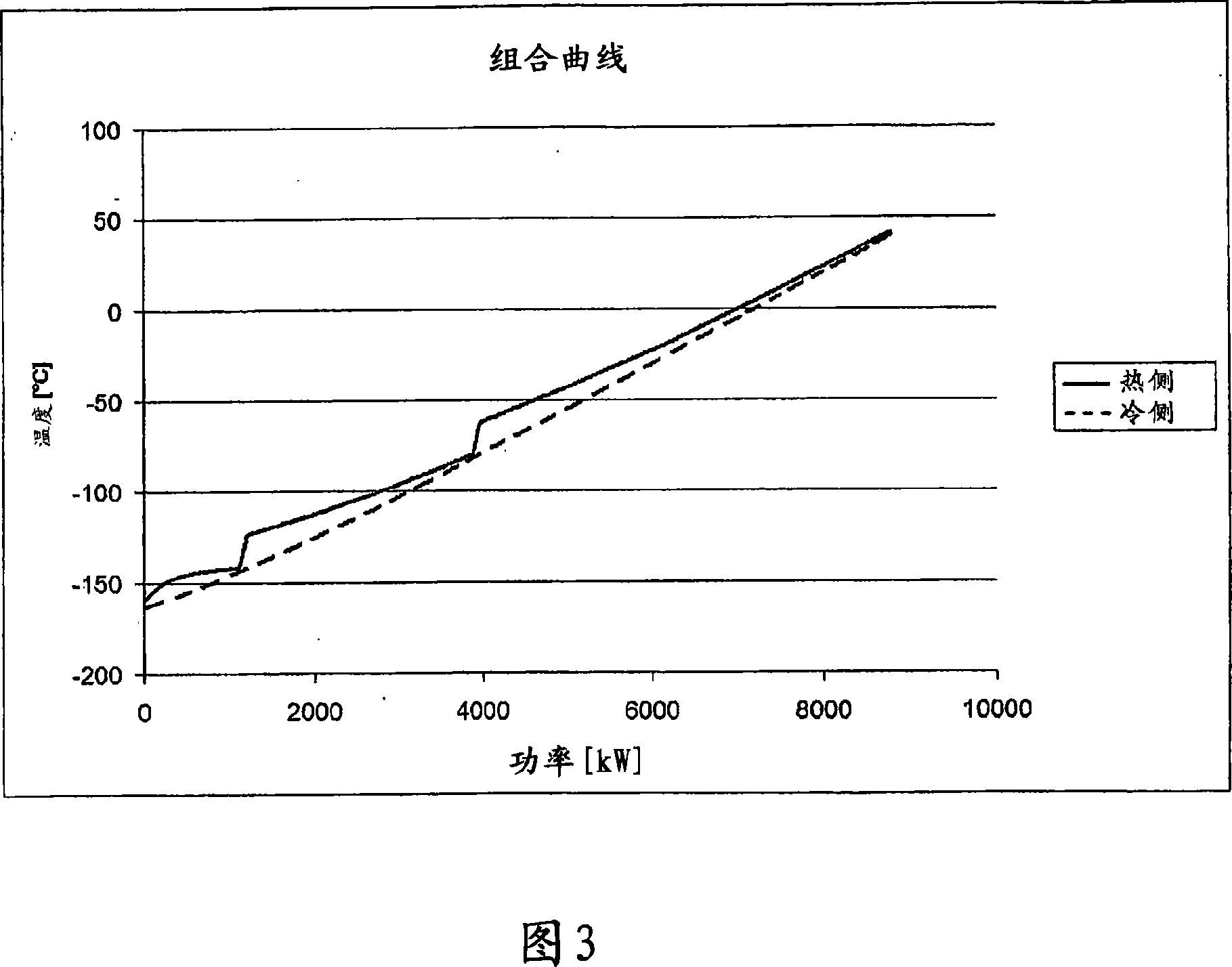
[0029] The choice of two expanders in series reduces the area of ​​loss of thermodynamic emissivity by introducing a new local temperature pinch. The above can be seen when looking at the combined curve of Figure 3 showing representative data for two expanders 8, 9 cycles in series. Note that even though the cooling capacity and temperature / pressure levels remai...


PUM


Abstract

A system for cooling a boil-off gas (BOG) stream prior to compression in a boil-off reliquefaction plant, comprising a line ( 10 ) for feeding BOG into a compressor ( 11; 11 '') prior to heat exchange with a closed-loop refrigeration system. The refrigeration system comprising compressors ( 2, 3, 4 ) and expanders( 8, 9 ) and a number of heat ex-changers for heat exchange with the BOG stream. The expanders ( 8, 9 ) are arranged in series. A precooler in the feed line ( 10 ) is fluidly connected ( 32, 33 ) to the closed-loop refrigeration system, whereby said BOG is pre-cooled in heat exchange with a portion of the coolant in the closed-loop refrigeration system prior to said compression.

Description

technical field [0001] The invention relates to the field of reliquefaction of boil-off gas of liquefied natural gas (LNG). More specifically, the present invention relates to a method and a system for cooling a boil-off gas stream as set forth in the preamble of independent claim 1 . technical background [0002] A common technique for delivering natural gas from the extraction side is to liquefy the natural gas at or near the extraction side and transport the liquefied natural gas to market in specially designed storage tanks aboard ships traveling at sea. [0003] The process of liquefying natural gas involves compressing and cooling natural gas to cryogenic temperatures (eg -160°C). Carriers for liquefied natural gas can thus transport large quantities of liquefied gas to their destinations. At the destination, the LNG is unloaded into specialized tanks onshore before being transported by road or rail on LNG loaders or regasified and transported eg by pipeline. [000...

Claims


Application Information

Patent Timeline
Patent Type & Authority Applications(China)
IPC IPC(8): F25J1/02F25B
CPCF25J2270/16F25J2230/20F25J1/005F25J2290/10F25J2230/30F25J2230/60F25J1/0025F25J1/0204F25J2230/08F25J1/0288F25J1/0072F25J1/0277F25J2230/04F25J1/02
Inventor C·J·鲁梅尔霍夫B·H·豪克达尔
Owner 海威KSE气体系统公司
Why Eureka
Try Eureka