Fuel cell emergency system

A fuel cell system and fuel cell technology, applied in the direction of fuel cells, fuel cell additives, fuel cell heat exchange, etc., can solve complex problems and achieve high system practicability

Inactive Publication Date: 2008-03-05
AIRBUS OPERATIONS GMBH
View PDF0 Cites 16 Cited by
  • Summary
  • Abstract
  • Description
  • Claims
  • Application Information

AI Technical Summary

Problems solved by technology

For this reason, integrating a ram air turbine into an aircraft is a complex process

Method used


Image

  • Fuel cell emergency system
  • Fuel cell emergency system

Examples


Embodiment Construction

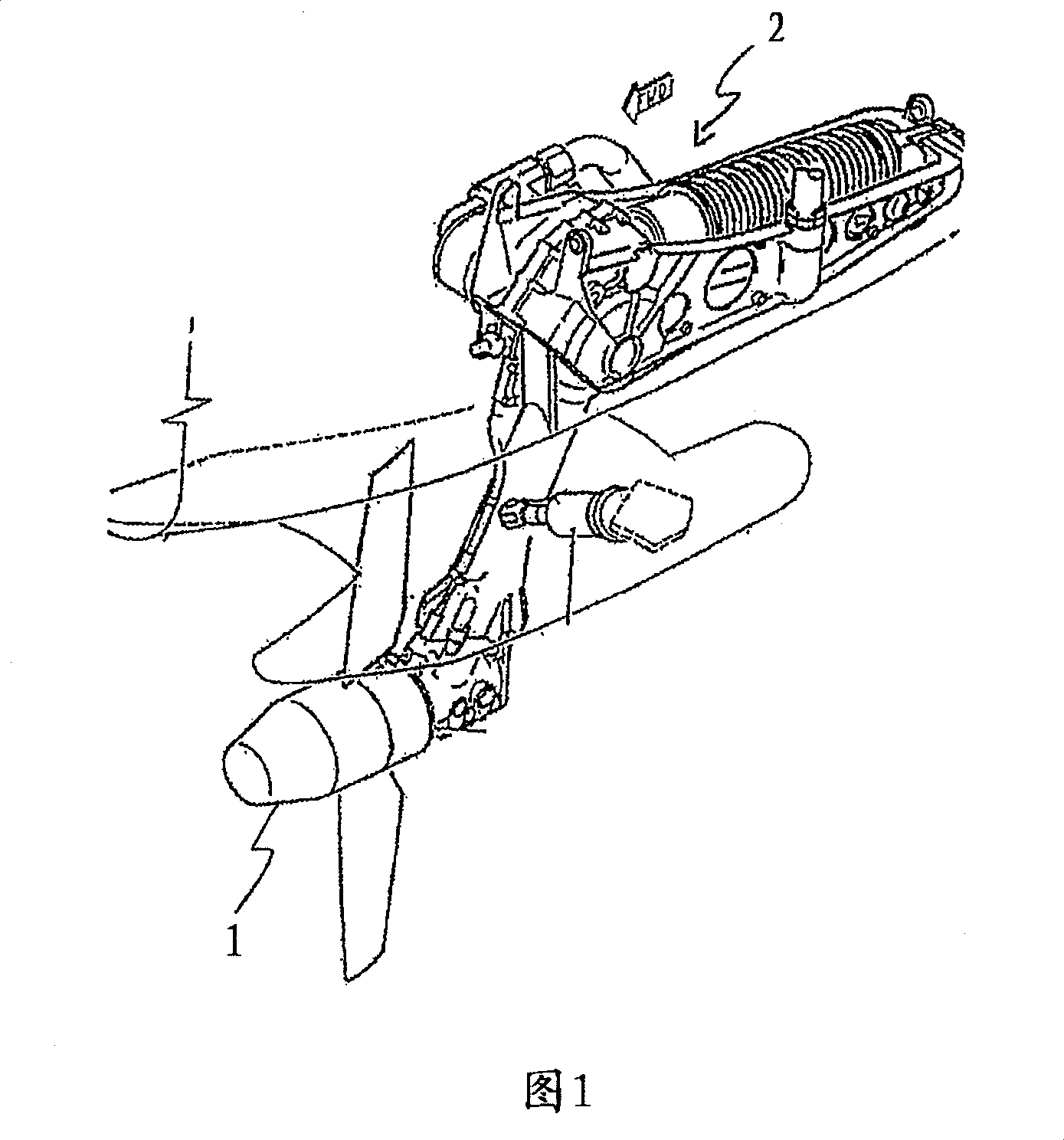
[0029] FIG. 1 shows an example diagram of a ramjet turbine, which mainly includes a rotor 1 and a hydraulic pump 2 . The ramjet turbine is retractable when inactive and opens mechanically in emergency situations such as failure of the engine, onboard hydraulics, or generator. The air flow hits the rotor, generating mechanical energy that drives the hydraulic pump 2 . Due to the complex opening mechanism, it must be able to withstand enormous mechanical stresses, and due to the rotating parts, the ramjet turbine and its installation have a complex mechanical construction. Ram air turbines and their operability are often not permanently monitored and therefore require additional maintenance work.

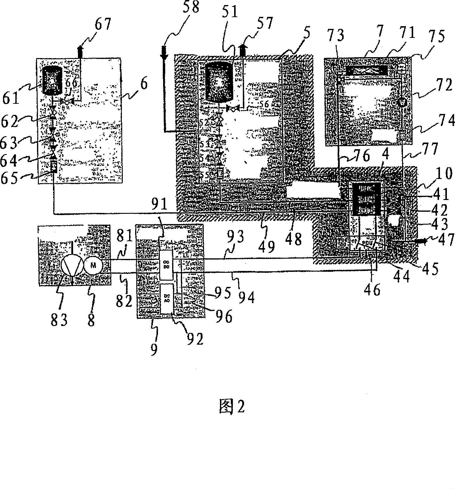
[0030] Fig. 2 shows a schematic diagram of a fuel cell emergency system according to an exemplary embodiment of the present invention. As clearly shown in Figure 2, the fuel cell emergency system includes metering valves 42, 43, a power distribution unit 46, switches and wires 44, 4...


PUM


Abstract

The system has a fuel cell stack (41) comprising a set of fuel cells, and oxygen and hydrogen tanks (51, 61) attached to the cell stack for supplying oxygen gas and hydrogen gas to the cells. The tanks (51, 61) are oxygen and hydrogen compressed gas cylinders, respectively. The cell stack is arranged in a pressurized and air-conditioned area of an aircraft, and a cooling unit (7) is provided for cooling the cell stack. An independent claim is also included for a method for energy-emergency supply in an aircraft.

Description

[0001] This application claims priority to US Provisional Patent Application 60 / 659 359, filed March 7, 2005, and German Patent Application 102005010399.5, filed March 7, 2005, the disclosures of which are incorporated herein by reference. technical field [0002] The invention relates to emergency power supplies for aircraft. In particular, the present invention relates to a fuel cell system for powering an aircraft, an aircraft including a corresponding fuel cell system, applications of the fuel cell system and a method of emergency power supply in an aircraft. Background technique [0003] In modern aircraft, a ram air turbine (RAT) is used to provide emergency power by creating a free flow towards the rotor should the engine, generator or hydraulic system fail. Here, the ram air turbine is located within the aerodynamic envelope when not in operation, but is opened mechanically in emergency situations. [0004] Depending on the system configuration of the aircraft, the ...

Claims


Application Information

Patent Timeline
Patent Type & Authority Applications(China)
IPC IPC(8): H01M8/00B64D41/00H02J9/06
CPCY02T90/32H01M2250/20H01M8/04007H01M8/04089H01M8/04365B64D41/007H01M8/04731Y02T90/36Y02E60/50H01M8/04201B64D2041/005Y02B90/10Y02T90/40B64D41/00H01M8/04313H01M8/04
Inventor 赫伯特·甘斯拉尔夫-亨宁·施托尔特福尔克尔·皮宗卡
Owner AIRBUS OPERATIONS GMBH
Why Eureka
Try Eureka