Oxygen emergency supply device

a technology for emergency supply and oxygen, which is applied in the field of oxygen emergency supply devices for aircraft, can solve the problems of inability to check the degree of oxygen container filling, the danger of burning out, and the inner pressure of the oxygen container being too high, so as to increase the operational reliability

a technology for emergency supply and oxygen, which is applied in the field of oxygen emergency supply devices for aircraft, can solve the problems of inability to check the degree of oxygen container filling, the danger of burning out, and the inner pressure of the oxygen container being too high, so as to increase the operational reliability

US20070283960A1Active Publication Date: 2007-12-13BE AEROSPACE SYST

Image

  • Oxygen emergency supply device
  • Oxygen emergency supply device

Examples


Embodiment Construction

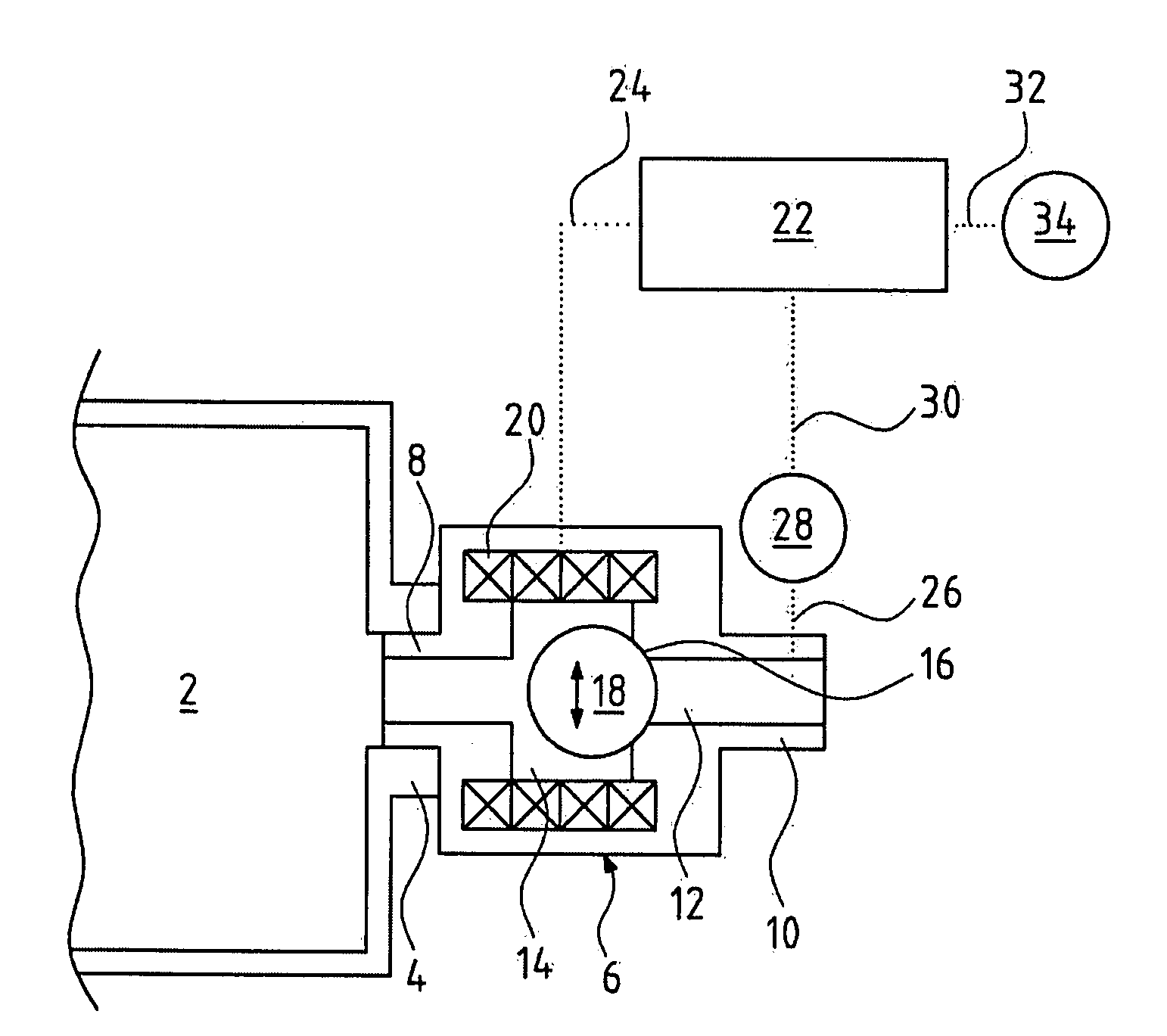
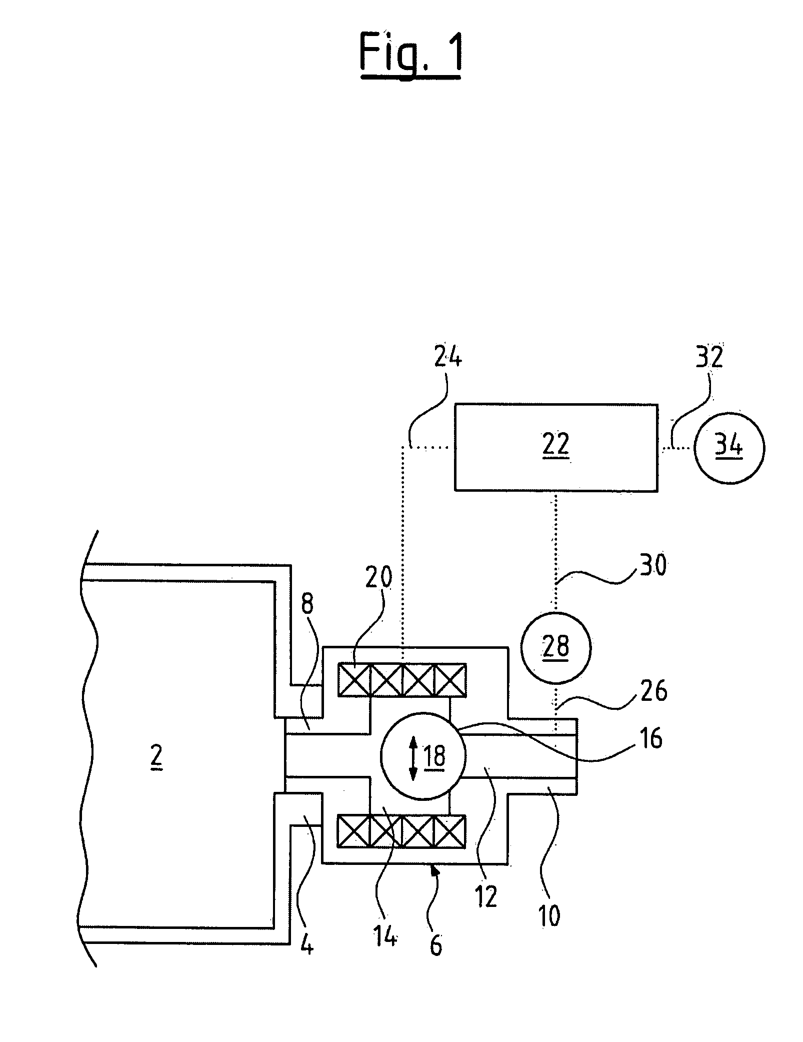
[0017]An oxygen pressure vessel 2 is represented in FIG. 1. This oxygen pressure vessel 2 comprises an open inlet- and outlet connection 4, to which a shut-off valve designed as a return valve 6 is connected. There, a first connection part 8 of the return valve 6 engages into the outlet- and inlet connection 4 of the oxygen pressure vessel 2. A connection conduit to a flow throttle, and ultimately to an oxygen mask (none of these represented in FIG. 1), is connected to a second connection part 10 of the return valve 6.

[0018]The return valve 6 is designed as an electromagnetically activatable ball-seat valve. A flow path 12 runs through the return valve 6 from the first connection part 8 to the second connection part 10, wherein the cross section of the flow path 12 widens within the valve housing to a valve chamber 14. The cross-sectional transition from the valve chamber 14 to the flow path 12 is conically chamfered at the side which faces the second connection part 10. This chamfe...


PUM


Abstract

An oxygen emergency supply device for an aircraft includes an oxygen pressure vessel, which is in fluid connection with at least one oxygen mask. Means for closing and opening the oxygen pressure vessel, means for pressure reduction, a pressure regulation device, and a flow throttle are provided in the conduit connection between the oxygen pressure vessel and the oxygen mask. The oxygen emergency supply device further includes a control device. A controllable shut-off valve forms the means for closing and opening the oxygen pressure vessel, the means for pressure reduction and a part of the pressure regulation device.

Description

BACKGROUND OF THE INVENTION[0001]The invention relates to an oxygen emergency supply device for an aircraft.[0002]Oxygen emergency supply systems for aircraft are known, in which oxygen stored in a pressurized gas bottle is led via a conduit connection to at least one oxygen mask. The pressurized gas bottles, which are applied with this, are closed by a shut-off valve, which may be actuated manually and downstream of which a pressure reducer is connected. A pressure regulation device is arranged in the conduit connection between the pressurized gas bottle and the oxygen mask, and subsequently downwardly regulates the oxygen pressure, reduced by the pressure reducer, to the demanded pressure required by a flow throttle connected upstream of the oxygen mask, in order to permit the required constant flow to reach the oxygen mask. The shut-off valve, the pressure reducer and the pressure regulation device, as well as the connections of these components in the conduit connection, disadva...

Claims


Application Information

Patent Timeline
13 Dec 2007
Publication
US20070283960A1
IPC
A61M16/00; A62B9/02
CPC
A62B7/14; B64D2231/02; B64D10/00
Inventors
MECKES, RUDIGER; RITTNER, WOLFGANG