Pulse fast edge conversion device

A technology of pulse fast and switching devices, which is applied in the directions of measuring devices, pulse processing, pulse shaping, etc., and can solve the problems of lack of pulse fast edge switching devices, etc.

Inactive Publication Date: 2008-03-12
UNIV OF ELECTRONICS SCI & TECH OF CHINA
View PDF0 Cites 9 Cited by
  • Summary
  • Abstract
  • Description
  • Claims
  • Application Information

AI Technical Summary

Problems solved by technology

However, for the synthetic pulse generation method, there...

Method used


Image

  • Pulse fast edge conversion device
  • Pulse fast edge conversion device

Examples


Embodiment Construction

[0020] The following describes preferred specific embodiments of the present invention in conjunction with the accompanying drawings. It is to be noted that similar parts are given similar reference numerals even though they appear in different drawings. Also, in the following description, when a detailed description of known functions and designs employed may obscure the subject matter of the present invention, these descriptions will be omitted here.

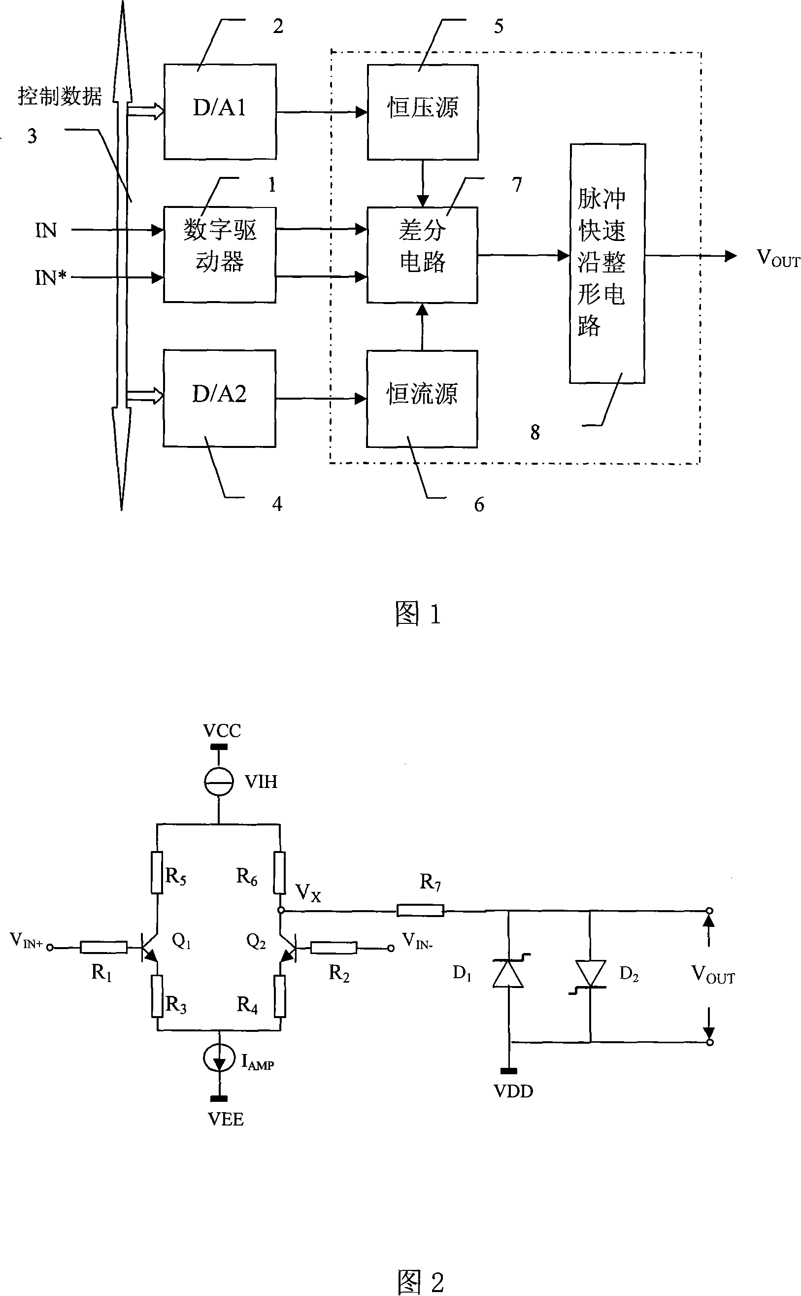
[0021] Fig. 1 is a functional block diagram of a specific embodiment of the pulse fast edge conversion device of the present invention, wherein the inside of the dotted line box is divided into the pulse fast edge conversion device of the present invention.

[0022] In this embodiment, the pulse fast-edge conversion device performs pulse fast-edge conversion on the programmable pulse signal generated by digital synthesis, and forms a programmable high-speed pulse generator together with peripheral circuits. Among them, the di...


PUM


Abstract

The invention discloses a pulse rapid converter device and consists of a pulse rapid shaping circuit that is made of forward and reverse snap off diodes, one end of the parallel forward and reverse snap off diodes is a rapid pulse signal output end that is connected with the shaping pulse signals through a resistance; the other end is connected with the pulse DC biasing power source end. When the snap off diode enters the reverse and stops from the forward flow, since the effect of minority, the snap off diode has large reverse current. When the reverse current disperses the minority inside the diode, the time is tq, the current inside the diode rapidly develops toward reverse saturation current with the time of tt, thus, the voltage on the load maintains within the tq period while rapidly increase or decrease within the tt time. The ascending/descending time of the pulse is quickened by the property of snap off of the snap off diode, the time thereof equals to the reverse restoring time of the snap off diode so as to realize rapid shaping of the pulse.

Description

technical field [0001] The invention belongs to the technical field of high-speed pulse signal generation, and specifically relates to a pulse fast edge conversion device. Background technique [0002] High-speed pulse signal is the key factor of the test system, and it is widely used in various electronics-related industries such as communication, radar, semiconductor manufacturing, integrated circuit testing, microprocessor testing and geological exploration. At the same time, there is a great demand for high-speed pulse signal sources in ultra-wideband communication, radar, guidance, and oscilloscope calibration. [0003] With the rapid development of microelectronics technology and the widespread use of radio frequency circuits, the performance indicators of pulse signal sources required for system testing have also been continuously improved. High-speed pulse generation technology has gradually become the basis for the development and testing of many high-speed circuits...

Claims


Application Information

Patent Timeline
IPC IPC(8): H03K5/01H03K5/12G01R1/28
Inventor 田书林付在明师奕兵王厚军黄建国
Owner UNIV OF ELECTRONICS SCI & TECH OF CHINA
Why Eureka
Try Eureka