Toroidal core current transformer comprising a phase compensation circuit

A technology of current transformers and ring iron cores, applied in voltage/current isolation, instruments, and measurement of electrical variables, etc.

Active Publication Date: 2008-03-12
SIEMENS ENERGY GLOBAL GMBH CO & KG
View PDF1 Cites 5 Cited by
  • Summary
  • Abstract
  • Description
  • Claims
  • Application Information

AI Technical Summary

Problems solved by technology

[0007] However, complex ratio errors occur in both types of toroidal core current transformers (voltage output, current output) due to losses in the tor

Method used


Image

  • Toroidal core current transformer comprising a phase compensation circuit
  • Toroidal core current transformer comprising a phase compensation circuit
  • Toroidal core current transformer comprising a phase compensation circuit

Examples


Embodiment Construction

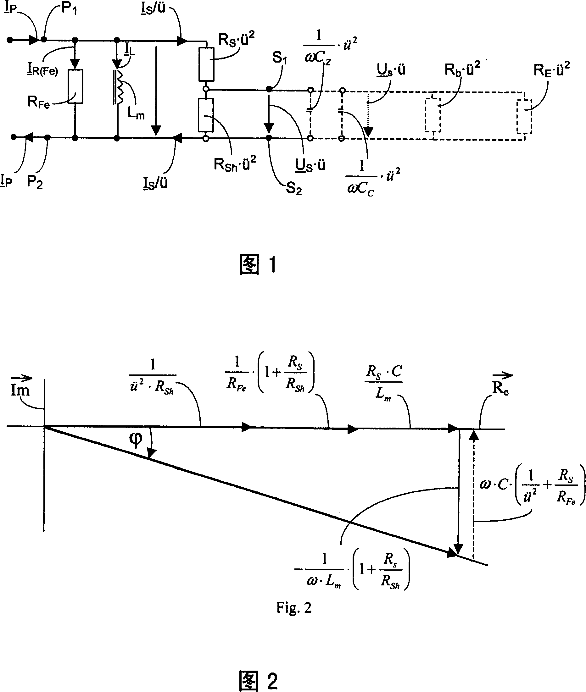
[0048]In the equivalent circuit of the primary side of the embodiment of the toroidal core current transformer of the present invention described in Fig. 1, R Fe Indicates the equivalent linear resistance to iron loss, L m Indicates the inductance of the current transformer. The resistance of the secondary winding is indicated by the symbol R S Indicated, and the measurement branch is indicated by the symbol R Sh express. In this case, as described in WO-A-98-58267, measuring shunt R Sh can be implemented as part of the second winding. Since the equivalent circuit diagram shown in Figure 1 refers to the primary side, the factor u 2 , that is, the number N of windings generated from the primary conductor P with the number of windings of the secondary winding N S The quotient of the transformation ratio u squared, is assigned to these resistors respectively. The figure also shows the capacitance C of the additional capacitor Z and line cable capacitance C C . In the e...


PUM


Abstract

Disclosed is a toroidal core current transformer comprising a primary conductor which penetrates the toroidal core and a secondary winding that is wound around the toroidal core. A measuring shunt (Rsh) or a load (Z b).

Description

technical field [0001] The invention relates to a toroidal core current transformer according to the preamble of the independent device claim and a method for determining a primary current by means of a toroidal core current transformer according to the preamble of the independent method claim . Background technique [0002] Toroidal core current transformers of this type can be used to convert high primary currents in the primary conductor into several times lower secondary currents in the secondary winding around the toroidal core by means of the toroidal core. So far, such toroidal core current transformers are used eg for revenue applications and for guarding purposes, where different types of current transformers (voltage output, current output) are used for revenue applications and for guarding purposes. [0003] Today, toroidal core current transformers with current output are often designed according to the IEC60044-1 standard and the IEC60044-6 standard, wherein ac...

Claims


Application Information

Patent Timeline
IPC IPC(8): G01R15/18
CPCG01R15/181
Inventor 鲁特哈特·明克纳约阿希姆·施密德罗尔夫·弗卢里
Owner SIEMENS ENERGY GLOBAL GMBH CO & KG
Why Eureka
Try Eureka