Superconductive cable and DC power transmission using the superconductive cable

一种超导电缆、超导导体的技术,应用在DC传输系统领域,能够解决电流大、温度过度上升、AC损耗大等问题

Inactive Publication Date: 2008-03-12
SUMITOMO ELECTRIC IND LTD
View PDF0 Cites 3 Cited by
  • Summary
  • Abstract
  • Description
  • Claims
  • Application Information

AI Technical Summary

Problems solved by technology

[0003] In the case of AC transmission using the above-mentioned superconducting cable, not only the AC loss due to inductance is large but also the current at the time of short circuit is so large that the temperature may rise excessively due to the loss at that time

Method used


Image

  • Superconductive cable and DC power transmission using the superconductive cable
  • Superconductive cable and DC power transmission using the superconductive cable
  • Superconductive cable and DC power transmission using the superconductive cable

Examples


example 1

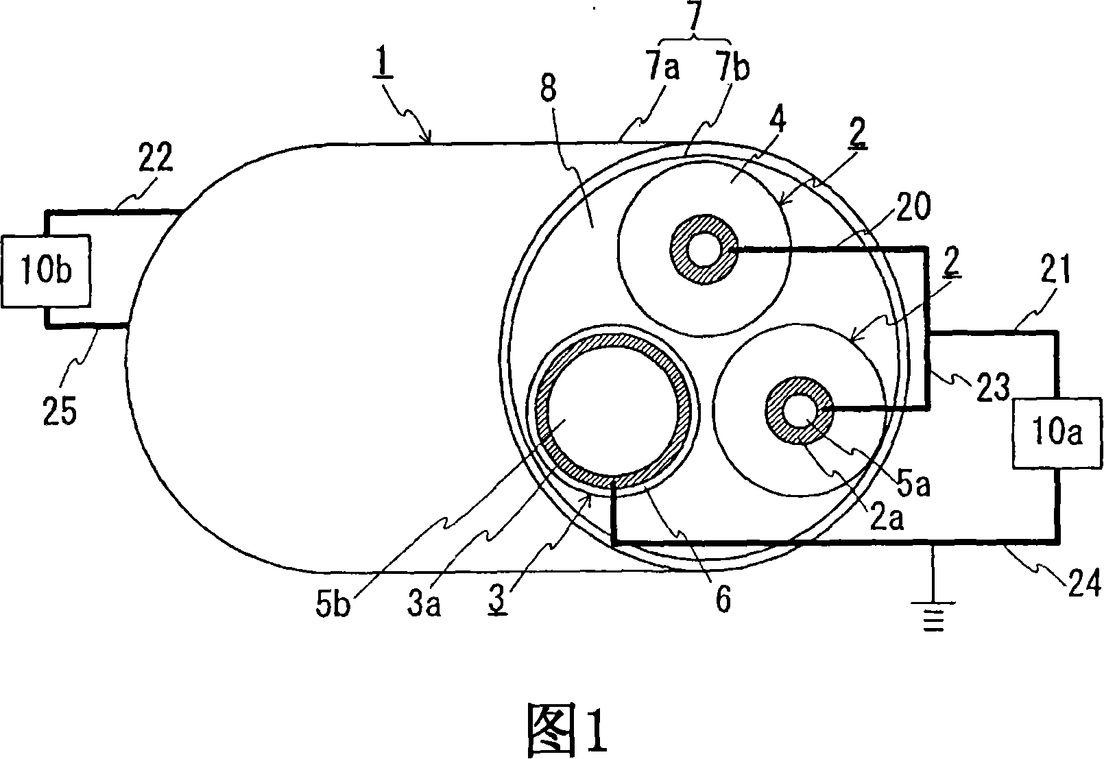
[0096] FIG. 1 is a schematic diagram showing a state in which a DC transmission line for unipolar transmission is constructed by using the superconducting cable of the present invention. In the following drawings, the same symbols denote the same components. The superconducting cable 1 is formed by twisting together two types of cores (two first cores 2 and one second core 3 ) having different structures and housing the twisted cores in a heat insulating tube 7 . More specifically, each first core 2 has a first superconducting layer 2a composed of a superconducting material at the inner peripheral side of the insulating layer 4 without a layer composed of a superconducting material at the outer peripheral side of the insulating layer 4 . The second core 3 is provided with a core part 5b at the central part side, a second superconducting layer 3a composed of a superconducting material is provided at the outer peripheral side of the core part 5b, and is not provided at the cent...

example 2

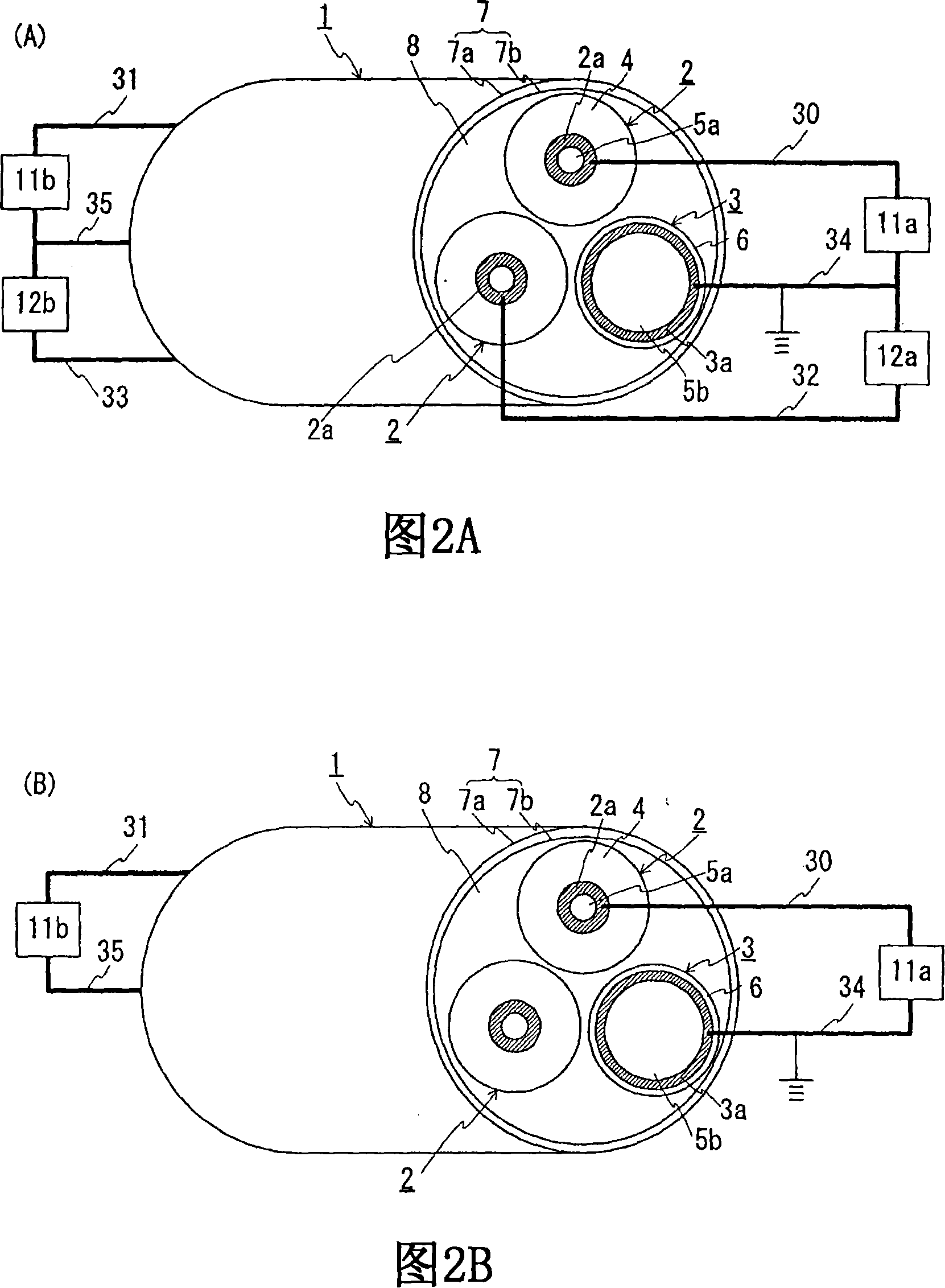
[0106]Next, the case where bipolar transmission is performed is explained. FIG. 2(A) is a schematic structural view showing a state in which a DC transmission line for bipolar transmission is constructed by using the superconducting cable of the present invention. FIG. 2(B) is a schematic configuration diagram showing a state in which a DC transmission line for unipolar transmission is constituted by using one of two first cores and a second core. The superconducting cable 1 used in Example 1 can also be used for bipolar transmission. For bipolar transmission, it is recommended to construct the transmission line as shown in Fig. 2(A). More specifically, one end of the first superconducting layer 2a provided in one of the two first cores 2 (in FIG. 2(A), the top first core 2) is connected to the DC-AC conversion 11a, the converter is connected to an AC system (not shown). The other end of the same first superconducting layer 2a is connected via a lead wire 31 to a DC-AC conv...

example 3

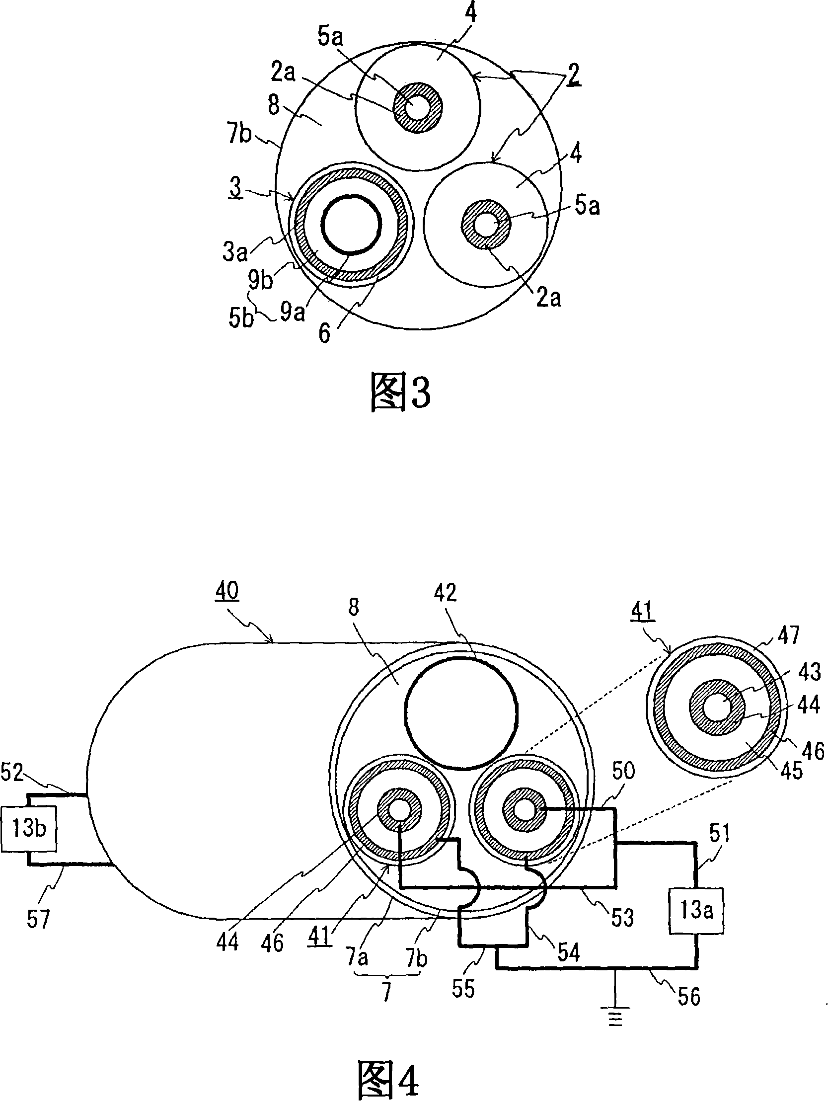
[0117] In the above-mentioned Embodiments 1 and 2, an explanation was given to the structure of the core member in which the stranded copper wire was used as the second core. However, a coolant circulation pipe may be used as the core member. 3 is a schematic cross-sectional view showing a superconducting cable of the present invention having a coolant circulation pipe inside a second superconducting layer of a second core. The second core 3 shown in this example has the same basic structure as that shown in Examples 1 and 2. The only difference is that a coolant circulation pipe 9a is provided as an inner core member of the core member 5b. An explanation is given below by focusing on this point.

[0118] In this example, the coolant circulation pipe 9a is formed using a corrugated stainless steel pipe. The insulating layer 9b is formed on the outer periphery of the coolant circulation pipe 9a by spirally winding a semi-synthetic insulating layer. In this example, in parti...


PUM

PropertyMeasurementUnit
electrical resistivityaaaaaaaaaa

Abstract

There are provided a superconductive cable which can easily be formed with twisted structure using a plurality of cable cores and a DC power transmission method using the superconductive cable. The superconductive cable (1) includes two types of cable cores (first core (2), second core (3)) having different structures which are twisted together and contained in an adiabatic tube (7). The first core (2) has a first superconductive layer (2a) used for an approach route or a polarity transmission in a DC power transmission and has no superconductive layer other than the first superconductive layer (2a). The second corer (3) has a second superconductive layer (3a) used for a return trip or a neutral conductor in DC power transmission and has no superconductive layer other than the second superconductive layer (3a). The second superconductive layer (3a) has an inner diameter greater than the outer diameter of the first superconductive layer (2).

Description

technical field [0001] The present invention relates to a superconducting cable formed by twisting together a plurality of cable cores and a DC transmission system including the superconducting cable. In particular, the present invention relates to a superconducting cable that can easily form a twisted structure. Background technique [0002] As an AC superconducting cable, a known three-core twisted type cable is formed by twisting three cable cores together. Fig. 7 is a cross-sectional view of a three-core twisted type cable for three-phase AC. The superconducting cable 100 has a structure in which three cable cores 102 are twisted together and accommodated in a heat insulating tube 101 . The heat insulation pipe 101 has a double pipe structure composed of an outer pipe 101a and an inner pipe 101b between which a heat insulating material (not shown) is provided. The space between the outer tube 101a and the inner tube 101b is evacuated. On the outer periphery of the th...

Claims


Application Information

Patent Timeline
Patent Type & Authority Applications(China)
IPC IPC(8): H01B12/08H01B12/16
CPCY02E40/642H01B12/16H01B12/06Y02E40/647Y02E40/60H01B12/08
Inventor 广濑正幸
Owner SUMITOMO ELECTRIC IND LTD
Why Eureka
Try Eureka