Differential lifting high-order tippler

A dumper and high-level technology, applied in the field of material unloading equipment, can solve problems such as high energy consumption, unreasonable design, and affecting the normal operation of equipment

Inactive Publication Date: 2008-03-19
唐志明
View PDF4 Cites 6 Cited by
  • Summary
  • Abstract
  • Description
  • Claims
  • Application Information

AI Technical Summary

Problems solved by technology

During the operation, each component is working under the condition of large torque, and the hydraulic drive cylinder is in frequent reciprocating motion, which will inevitably cause fatigue damage to parts and affect the...

Method used


Image

  • Differential lifting high-order tippler
  • Differential lifting high-order tippler
  • Differential lifting high-order tippler

Examples


Embodiment Construction

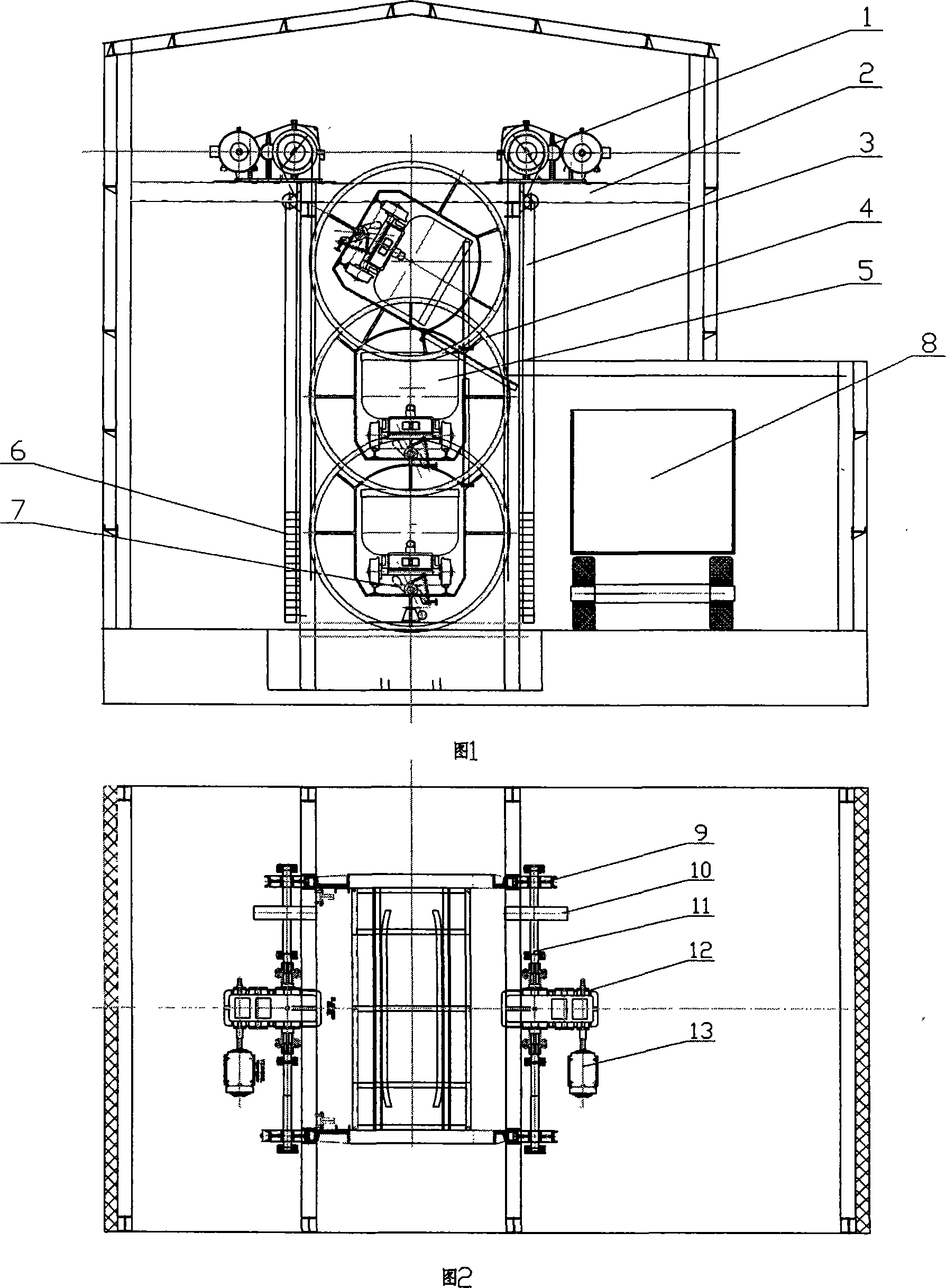
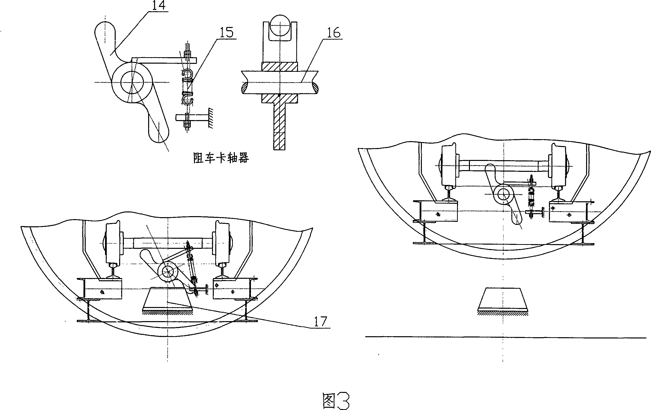
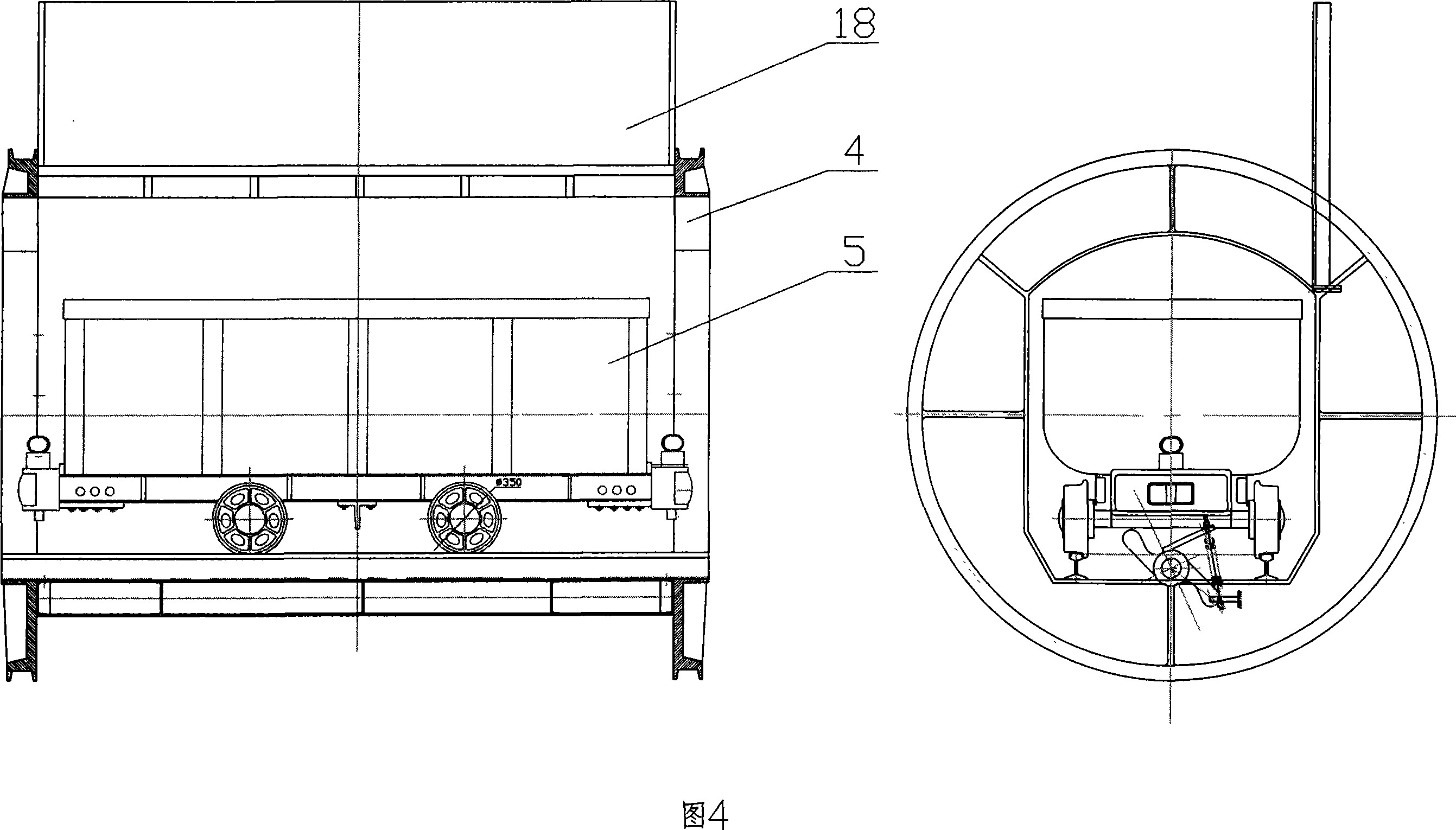
[0012] In order to clearly illustrate the technical features of the solution, the solution will be described below through a specific implementation mode combined with the accompanying drawings.

[0013] It can be seen from the accompanying drawings that the differential lifting high-position dumper of this program consists of a steel structure lifting bracket and a workshop assembly (2), an electric motor (13), a reduction box (12), a drive shaft (11), and a friction wheel (9 )composition. The lifting drive device (1) composed of the electric motor (13), reduction box (12), drive shaft (11), and friction wheel (9) is symmetrically arranged above the steel structure lifting bracket and the workshop assembly (2). One end of the hoisting wire rope (3) is connected to the round rolling cage (4), and the other end is wound three times on the friction wheel (9), so that the end is drooped and anchored with the balance weight (6). Winding three circles on the wheel (9) can make the...


PUM


Abstract

The invention discloses a differential elevation high dumper which essentially consists of elevation drive devices, a steel structure elevation support and a factory building combination, an elevation steel wire rope, a round rolling cage, a mine car, a counter weight, a friction wheel, a drive shaft, a gear box and a motor. The invention is characterized in that two elevation drive device are symmetrically arranged above the support. The elevation steel wire rope winding the friction wheel for three rounds can equally load the weight of the round rolling cage and that of the mine car body on both ends of the elevation steel wire rope by the counterweight, and produce tension and friction drive, which is one of the functions. Because both ends of the steel wire rope are equally loaded, the complete dumper starts to run, only net weight of the bulk materials in the mine car needs to be considered for the power of the motor. Therefore, the energy saving of the invention is obvious, which is the second function. The cycle process including starting, accelerating, constant-speed, differential, decelerating running and stopping to reversely run of the two sets of elevation drive devices are electrically and logistically controlled.

Description

Technical field: [0001] The invention relates to a material unloading device, in particular to a high-position dumper for high-point unloading of materials loaded in a material vehicle. Background technique: [0002] The dumper is a kind of material unloading equipment that is widely used in the material yard at present. It can turn over the material truck carrying a large amount of bulk materials so that the materials can be loaded into the designated place or loading tool. The dumpers currently used by people include tank tippers, hydraulic high-position dumpers, etc. These dumpers dump the material trucks to realize the work of dumping materials through special dumpers provided on them. The invention patent with the application number 200710013670.7 has announced a high-position dumper which adopts a hydraulically driven oil cylinder, a pivoting arm for parking a material vehicle, a base arranged on the foundation, and a support on the base. During the operation, each co...

Claims


Application Information

Patent Timeline
IPC IPC(8): B65G67/48
Inventor 唐志明
Owner 唐志明
Why Eureka
Try Eureka