Floor drain

A floor drain and rotor sleeve technology, which is applied in the field of drainage floor drains, can solve the problems of unfavorable service life of blade generators, poor power generation efficiency and effect, and large vibration of blades, etc., and achieve the effects of reduced impact, high utilization rate, and stable rotation

Active Publication Date: 2017-08-18
霍永军
View PDF7 Cites 1 Cited by
  • Summary
  • Abstract
  • Description
  • Claims
  • Application Information

AI Technical Summary

Problems solved by technology

[0005] However, using the impact of water and solids on the blades to make the blades rotate, the efficiency of water and solids converting their own kinetic energy into the kinetic energy of the blades is very low, and the power generation efficiency and effect are not good, and water and solids have an impact on the blades. The impact of the blade will inevitably cause greater vibration of the blade, which is detrimental to the service life of the blade and the generator

Method used


Image

  • Floor drain
  • Floor drain
  • Floor drain

Examples


Embodiment Construction

[0037] In order to enable those skilled in the art to better understand the technical solutions of the present invention, the present invention will be described in detail below in conjunction with the accompanying drawings and specific embodiments.

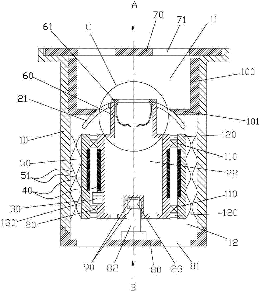
[0038] Such as figure 1 As shown, the embodiment of the present invention discloses a floor drain, which can be installed on the ground that needs drainage, such as bathrooms. The floor drain includes a main body 10 , a stator core 20 , a rotor sleeve 30 and a battery 130 . The main body 10 is formed with a cavity with an open upper end and a drainpipe at the lower end. Water enters the cavity from the upper end of the main body 10 and is discharged from the lower end of the main body 10, and then enters the drainpipe; the stator core 20 is set in such a way that its rotation is restricted In the cavity; the rotor sleeve 30 is set on the stator core 20, and the bearing 110 and the sealing ring 120 are installed between the rotor...


PUM


Abstract

The invention discloses a floor drain, which comprises a main body, stator cores, rotor sleeves and a storage battery, wherein an accommodating cavity with upper end provided with an opening and lower end communicating with a drainage pipe is formed in the main body; the stator cores are arranged in the accommodating cavity; the rotor sleeves sleeve the stator cores and are capable of rotating relatively to the stator cores; a pair of electromagnetic pairs, capable of causing electromagnetic stimulation, are arranged on the inner wall of each rotor sleeve and the outer wall of each stator core, so that electric motor generators are defined by the rotor sleeves and the stator cores; the storage battery is in charge of supplying power for rotation of the rotor sleeves when the electric motor generators serve as motors, and the storage battery is made to accumulate power along with the rotation of the rotor sleeves when the electric motor generators serve as generators, wherein at least one spiral guide groove is at least formed in the outer wall of each rotor sleeve, so that spiral passages are defined by the outer walls of the rotor sleeves and an accommodating cavity wall of the accommodating cavity; and the rotor sleeves are driven to rotate by water which flows through the spiral passages, and the electric motor generators serve as the generators so that the storage battery is made to accumulate the power.

Description

technical field [0001] The invention relates to the technical field of water supply and drainage, in particular to a floor drain for drainage. Background technique [0002] The floor drain is an important interface connecting the water end and the drainage piping system. The floor drain in the prior art is easy to cause blockage to itself or the drain because it is easy to accumulate solid matter and hair and other substances inside. [0003] In order to solve the above problems, the Chinese patent with the patent number CN202124901U provides an energy-saving and environmentally friendly unobstructed floor drain, which is provided with a fixed grinding disc, a rotating grinding disc, a motor, a generator, a storage battery and an annular diversion groove. The battery charges the motor to drive the rotating grinding disc to rotate relative to the fixed grinding disc to crush solid objects. After the fixed objects are crushed, they are accelerated through the annular guide gr...

Claims


Application Information

Patent Timeline
Patent Type & Authority Applications(China)
IPC IPC(8): E03F5/04F03B13/00
CPCE03F5/0407F03B13/00F05B2220/706
Inventor 霍永军
Owner 霍永军
Why Eureka
Try Eureka