Yarn feeding device for computer flat machine

A technology of yarn feeding device and computerized flat knitting machine, which is applied in textiles and papermaking, weft knitting, knitting, etc. It can solve problems affecting the design of knitting patterns, complex transmission mechanism, and quantity limitation, and achieve superior knitting performance and simple transmission structure. , the effect of force balance

Inactive Publication Date: 2008-03-19
冯加林 +1
View PDF0 Cites 3 Cited by
  • Summary
  • Abstract
  • Description
  • Claims
  • Application Information

AI Technical Summary

Problems solved by technology

Therefore, the transmission mechanism is extremely complicated and the cost is very high.
Since each motor and the corresponding transmission mechanism require a certain space, the number of shuttle boxes on the shuttle bar is limited, thus affecting the design of the knitting pattern

Method used


Image

  • Yarn feeding device for computer flat machine
  • Yarn feeding device for computer flat machine

Examples


Embodiment Construction

[0015] The present invention will be further described below in conjunction with embodiment.

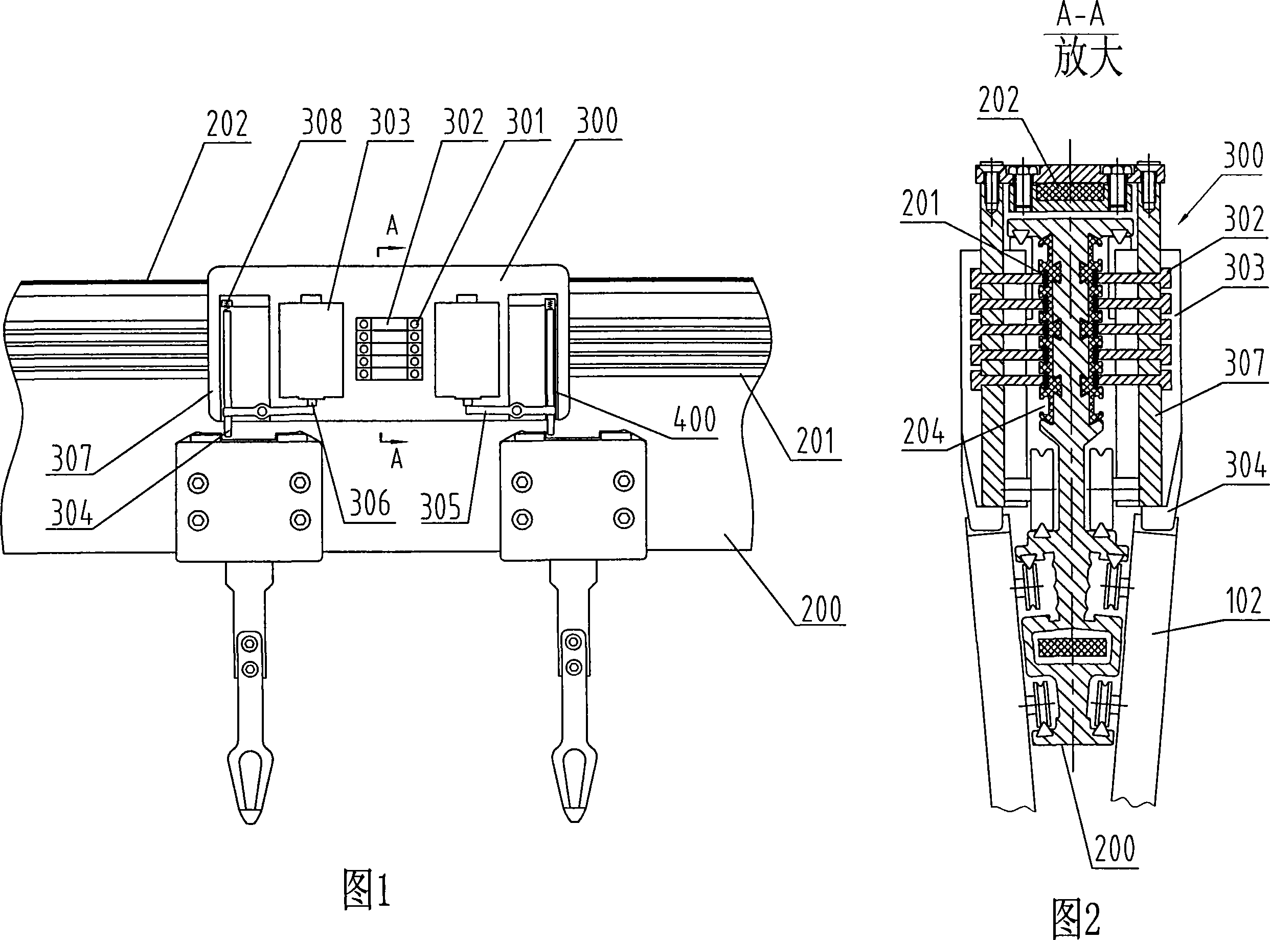
[0016] 1 and 2, the shuttle box control mechanism 300 is placed on both sides of the upper part of the shuttle bar 200, the shuttle box 102 is placed on the lower side of the shuttle bar 200, and the shuttle box control mechanism 300 is connected to the shuttle box 102 through the latch 304 on it , so that it moves along the shuttle bar 200 together.

[0017] Shuttle box control mechanism 300 is mainly made up of carbon brush 301, electromagnet 303, tab 304, tab shift fork 305, return spring 308, and base plate 307 etc. The electromagnet 303 is fixed inside the bottom plate 307 . The tab 304 is slidably connected to a slot 400 inside the bottom plate 307 . One end of the return spring 308 is connected to the bottom of the slot, and the other end is in contact with the upper end of the tab 304 . The carbon brush 303 is fixed on the bottom plate 307 through a carbon brush seat 301 , ...


PUM


Abstract

The present invention relates to a yarn feeding device of a computerized knitting machine and has the technical proposal that the present invention comprises a shuttle bar, a shuttle box and a shuttle box controlling mechanism, wherein, the shuttle box controlling mechanism is arranged on two sides of the upper part of the shuttle bar, the shuttle box is arranged on two sides of the lower part of the shuttle bar, and the shuttle box controlling mechanism is connected with the shuttle box in a rotary way through a clip flap on the controlling mechanism to drive the shuttle box to move together along the shuttle bar. The present invention has the advantages that the shuttle box controlling mechanism formerly arranged on the nose connecting frame is arranged on the shuttle bar, on one hand, the weaving wire on a wire frame is directly guided on the shuttle box, and the weaving wire is not required to be bended, thereby, the mutual entanglement and whipping together cannot be caused, the suffered pulling force is small and the force distribution is uniform, thus being favorable to the improvement of the quality of weaving; on the other hand, the controlling of the shuttle box on the shuttle bar is executed by the shuttle box controlling mechanism through a computer order, thereby, the driving structure is simple, and the occupied space is small, but the operation is accurate and effective, more shuttle boxes can be arranged on the shuttle bar to meet the needs of more weaving patterns and more complex weaving patterns, so as to provide superior knitting performance for the computerized knitting machine, and to greatly increase the performance-to-price ratio.

Description

technical field [0001] The invention relates to a computerized flat knitting machine, in particular to a yarn feeding device for a computerized flat knitting machine. Background technique [0002] The structure of the current computerized flat knitting machine and the guidance of the braided wire are shown in Figure 4. A number of thread take-up frames 100 are evenly distributed on the upper end of the knitting machine, and a thread frame 101 is respectively arranged on both sides thereof. In the frame 107, and driven by the head 104. Participate in the coil 105 of braiding yarn in each braiding machine rear side or on the top, and the thread end on it is drawn out by a corresponding thread take-up frame 100 and all will be led to by the side thread frame 101 of frame one side. Corresponding each shuttle box 102 on the shuttle bar. [0003] The above-mentioned leading thread method makes the braided yarn be bent into the shuttle box, and the braided yarn receives a large ...

Claims


Application Information

Patent Timeline
Patent Type & Authority Applications(China)
IPC IPC(8): D04B15/00D04B15/48
Inventor 冯加林巫友群
Owner 冯加林
Why Eureka
Try Eureka