Viscous fluid-sealed damper

A technology of viscous fluid and shock absorber, which is applied in the field of shock absorption, and can solve the problems of poor bonding between the surrounding wall part 11 and the cover part 6, leakage of viscous fluid 10, long production time, etc.

Inactive Publication Date: 2008-03-19
SEKISUI POLYMATECH CO LTD
View PDF2 Cites 5 Cited by
  • Summary
  • Abstract
  • Description
  • Claims
  • Application Information

AI Technical Summary

Problems solved by technology

However, since the adhesive is used to fix the components, the production time is long and the cost increases
Moreover, when the viscous fluid 10 is sealed in the airtight container 2, if the viscous fluid 10 adheres to the fixed attachment surface between members, it will cause poor adhesion between the peripheral wall portion 11 and the cover portion 6, thereby causing leakage of the viscous fluid 10. reason

Method used


Image

  • Viscous fluid-sealed damper
  • Viscous fluid-sealed damper
  • Viscous fluid-sealed damper

Examples


no. 1 approach

[0056] First Embodiment (Fig. 1 to Fig. 3)

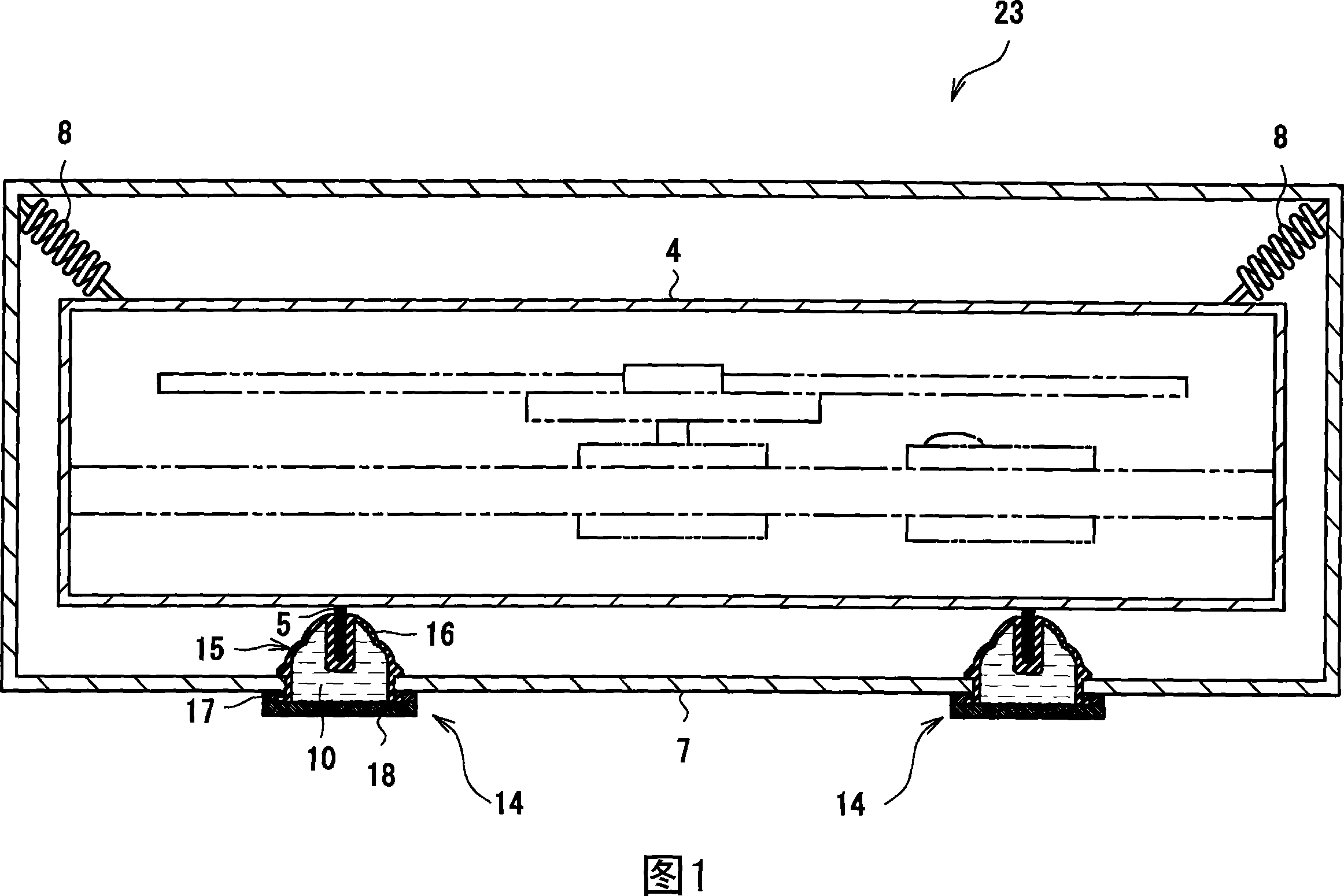
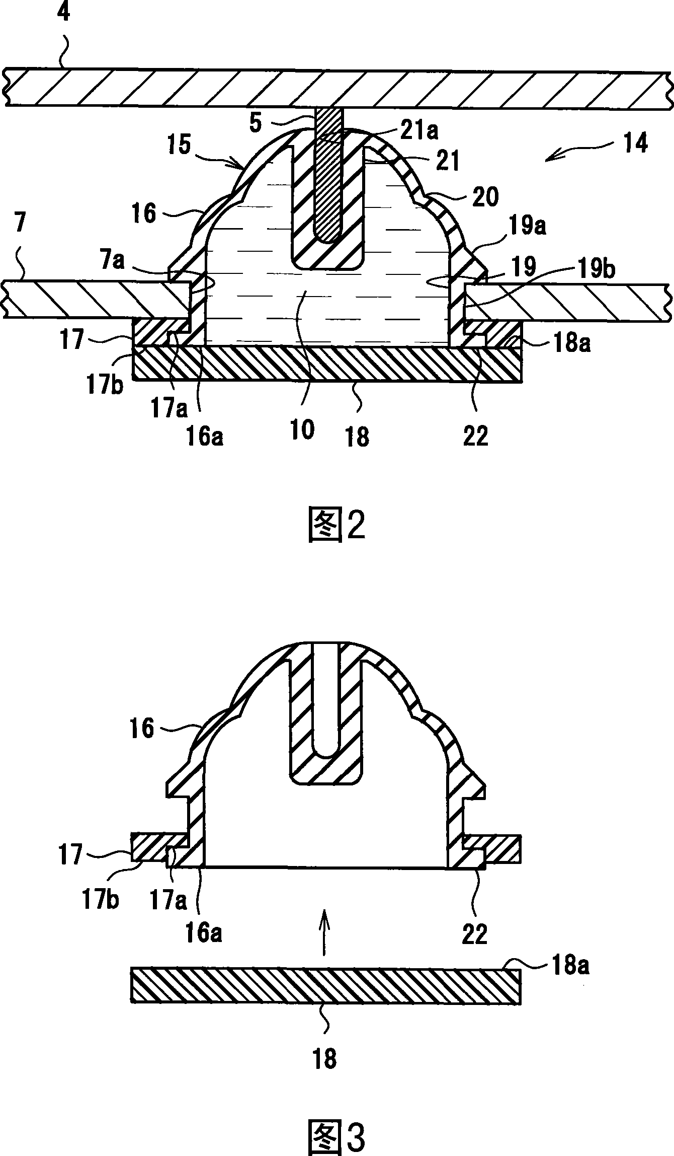
[0057] The viscous fluid-encapsulated damper 14 according to the first embodiment is shown in FIGS. 1 to 3 . The viscous fluid-enclosed shock absorber 14 of the first embodiment has a structure in which the viscous fluid 10 is enclosed in an airtight container 15 . The airtight container 15 is composed of a container body 16 , a sealing member 17 and a cover 18 .

[0058] The container body 16 is formed of a rubber-like elastic body, more specifically, butyl rubber, and has a hollow cup shape with one end open. The peripheral wall part 19, the flexible part 20, and the center attachment part 21 are formed from the opening end 16a side. Wherein, a flange portion 22 protruding outward is provided on the lower end side of the peripheral wall portion 19 along the entire circumference, and a protrusion 19a having an annular slope extending outward from the upper end side to the lower end side is provided on the upper end thereof. Betw...

no. 2 approach

[0074] Second Embodiment (Fig. 4, Fig. 5A, Fig. 5B)

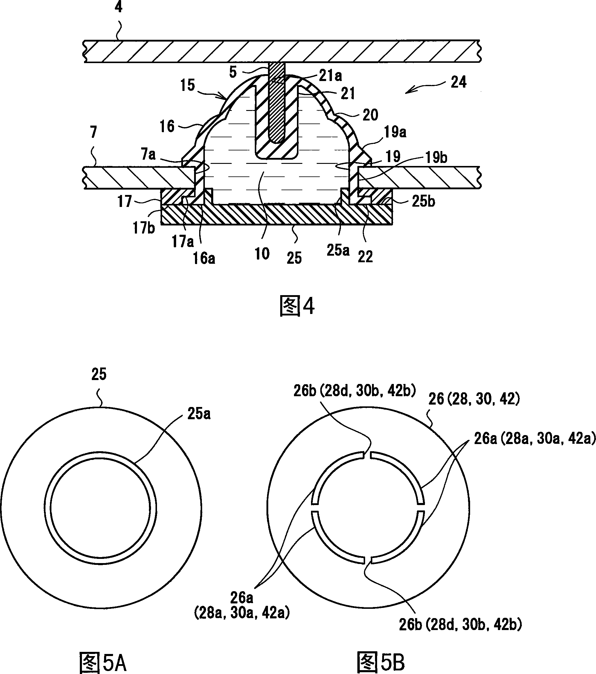
[0075] Encapsulation of the viscous fluid of the second embodiment into the damper 24 is shown in FIG. 4 , FIG. 5A , and FIG. 5B . The viscous fluid filled damper 24 in the second embodiment differs from the viscous fluid filled damper 14 in the first embodiment in the structure of the cover body 25 . The rest of the structure and its functions and effects are the same as those of the first embodiment.

[0076] The lid body 25 is formed with an endless annular protruding wall portion 25a that protrudes into the container body 16 and contacts the inner peripheral surface of the peripheral wall portion 19 of the container body 16 ( FIG. 5A ). The height of the protruding wall portion 25 a is the same as the thickness of the sealing member 17 . That is, the outer peripheral surface of the opening end 16a of the container body 16 is pressed by the sealing member 17 for compressing and holding the flange portion 22 of the peri...

no. 3 approach

[0082] Third Embodiment (FIG. 6)

[0083] Encapsulation of the viscous fluid in the shock absorber 27 of the third embodiment is shown in FIG. 6 . The viscous fluid filled damper 27 in the third embodiment differs from the viscous fluid filled damper 24 in the second embodiment in the structure of the cover body 28 . The rest of the structure and its functions and effects are the same as those of the second embodiment and the first embodiment.

[0084] Like the lid body 25 of the second embodiment, the lid body 28 is formed with an endless ring-shaped protruding wall portion 28a, and the protruding wall portion 28a protrudes into the interior of the container body 16 and is aligned with the inner periphery of the peripheral wall portion 19 of the container body 16. surface contact. Furthermore, a portion facing the fixed attachment surface 17b of the seal member 17 constitutes a fixed attachment surface 28b. However, the inner surface 28c of the lid body 28 is provided as a...


PUM


Abstract

Provided is a viscous fluid-sealed damper which helps to achieve an increase in degree of freedom in terms of the selection of the material of a sealing container, which can be produced with high production efficiency, and which helps to avoid leakage of the viscous fluid. A lid member (18) is fixed to a container main body (16) while compressing and holding a flange portion (22) between a sealing member (17) and the lid member (18), so an opening end (16a) of the container main body (16) can be sealed with the lid member (18) without having to effect fixation through fusion-bonding as in the prior art, and the degree of freedom in terms of material selection can be increased. Further, if the container main body (16) is formed of a butyl rubber, the container main body (16) can be fixed to the lid member (18) without using any adhesive, so it is possible to achieve a reduction in production time and in cost. Further, it is possible to avoid leakage of the viscous fluid (10) due to defective adhesion.

Description

technical field [0001] The present invention relates to the damping technology of disk devices such as optical disk devices and optical disk devices used in audio equipment, video equipment, information equipment, various precision instruments, etc. for vehicles and civilian use, and in particular, relates to a vibration reduction technology for reducing vibration caused by motors. The viscous fluid that is vibrated by the supporting body, such as the mechanical chassis composed of the optical pickup, the optical disc holder, etc., is enclosed in the shock absorber. Background technique [0002] A magnetic disk device is a precision device that brings an optical pickup or the like close to a magnetic disk that is rotated at high speed by a motor, and records or reproduces information on the magnetic disk. Since it cannot withstand external shocks from the outside of the device or internal shocks caused by the rotation of the eccentric disk, it is necessary to prevent malfunc...

Claims


Application Information

Patent Timeline
Patent Type & Authority Applications(China)
IPC IPC(8): G11B33/08F16F9/10
CPCF16F2230/105F16F9/103F16F15/00F16F15/16
Inventor 都泽理惠大木淳次
Owner SEKISUI POLYMATECH CO LTD
Why Eureka
Try Eureka