Compressor motor magnet magnetization method

A technology of compressors and magnets, which is applied in the direction of magnetic circuits, electromechanical devices, magnetic objects, etc., and can solve problems such as uneven arrangement of magnet polarity and incomplete magnetization of magnets

Inactive Publication Date: 2011-10-12
SAMSUNG ELECTRONICS CO LTD
View PDF3 Cites 0 Cited by
  • Summary
  • Abstract
  • Description
  • Claims
  • Application Information

AI Technical Summary

Problems solved by technology

[0008] However, during the magnetization of such conventional magnets, an excessively large rotating magnetic field is formed due to the high magnetization power applied to the coil, and the rotor is in the stator during the magnetization of the magnet due to the influence of such a rotating magnetic field. Rotate or shake freely, so there is a problem that the polarity arrangement of the magnet becomes uneven when magnetized
[0009] Furthermore, the above-mentioned magnet and the above-mentioned stator core are arranged to have approximately the same height and length as each other, but in this structure, there is a problem that the magnetic field formed in the stator during magnetization affects the upper and lower end portions of the magnet. Small, so part of magnetization is not completed on the upper end side and the lower end side of the magnet

Method used


Image

  • Compressor motor magnet magnetization method
  • Compressor motor magnet magnetization method
  • Compressor motor magnet magnetization method

Examples


Embodiment Construction

[0024] Hereinafter, a preferred embodiment according to the present invention will be described in detail with reference to the accompanying drawings.

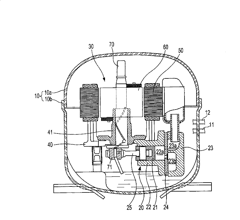
[0025] First, if figure 1 As shown, the appearance of the compressor according to this embodiment is formed by combining the upper container 10a and the lower container 10b with each other to form a sealed container 10, and one side and the other side of the sealed container 10 are respectively provided with guides for guiding the refrigerant. A suction pipe 11 to the inside of the sealed container 10 and a discharge pipe 12 for guiding refrigerant compressed inside the sealed container 10 to the outside of the sealed container 10 .

[0026] In addition, a compression unit 20 for performing a compression action of the refrigerant and a motor 30 for providing a driving force based on the compression action of the refrigerant are provided inside the sealed container 10 .

[0027] Among them, the above-mentioned compression unit...


PUM


Abstract

The present invention provides a magnetic iron magnetizing process of a compressor motor, which is capable of uniformly arranging magnetism of magnetic irons and uniformly magnetizing magnetic irons at entire area even in the state that a motor allocated for compressor has been assembled, when magnetization is executed on magnetic irons arranged at a rotor of the motor. For the process in accordance with the present invention, the compressor motor comprises a stator which is fixed to a spider is wound internally with coils and a rotor which can be rotatablely arranged in the stator and is provided with a plurality of magnetic irons at the outer circumference sides in the alternating polarity manner. Under the state that the motor has been completely assembled, the magnetic irons mentionedabove are magnetized by applying a magnetizing supply power to the coils. During the magnetization process of the magnetic irons, the rotor is supported in fixed manner and is prevented from freely moving, and a magnet body element longer than the magnetic irons is inserted between the rotor and the stator.

Description

technical field [0001] The present invention relates to a magnet magnetization method of a compressor motor, and more particularly, to a magnet magnetization method of a compressor motor capable of effectively magnetizing a magnet provided in a rotor of the compressor motor even when the motor is assembled. Background technique [0002] The compressor for compressing the refrigerant generally used in the refrigerating cycle of refrigerators or air conditioners forms an appearance through a sealed container, and a compression unit for compressing the refrigerant and a compressor for supplying refrigerant are arranged inside the sealed container. Compression of the refrigerant drives the motor. [0003] The above-mentioned motor includes: a stator fixed to a frame inside the hermetic container and around which a coil is wound; a rotor provided inside the stator and rotated by electric interaction with the above-mentioned stator; and a rotating shaft configured as a press It e...

Claims


Application Information

Patent Timeline
Patent Type & Authority Patents(China)
IPC IPC(8): H02K15/03H02K1/27H01F13/00
CPCH02K1/28H02K1/278H02K7/04H02K15/03H01F13/003F04B17/03F04B35/04
Inventor 卢兴均
Owner SAMSUNG ELECTRONICS CO LTD
Why Eureka
Try Eureka