Magnetic lag synchronous motor and its making technology

A synchronous motor and hysteresis technology, applied in the direction of synchronous motors for single-phase current, manufacturing motor generators, electric components, etc., can solve problems such as difficult processing, high noise, complex winding structure, etc., without damaging internal components Devices, improved work efficiency, novel structure effects

Active Publication Date: 2008-03-19
余国华
View PDF0 Cites 12 Cited by
  • Summary
  • Abstract
  • Description
  • Claims
  • Application Information

AI Technical Summary

Problems solved by technology

The core slot and winding structure of the hysteresis synchronous motor mentioned above are relatively complex, bulky, an

Method used


Image

  • Magnetic lag synchronous motor and its making technology
  • Magnetic lag synchronous motor and its making technology
  • Magnetic lag synchronous motor and its making technology

Examples


Example Embodiment

[0024]The present invention will be further described in detail below with reference to the embodiments of the drawings.

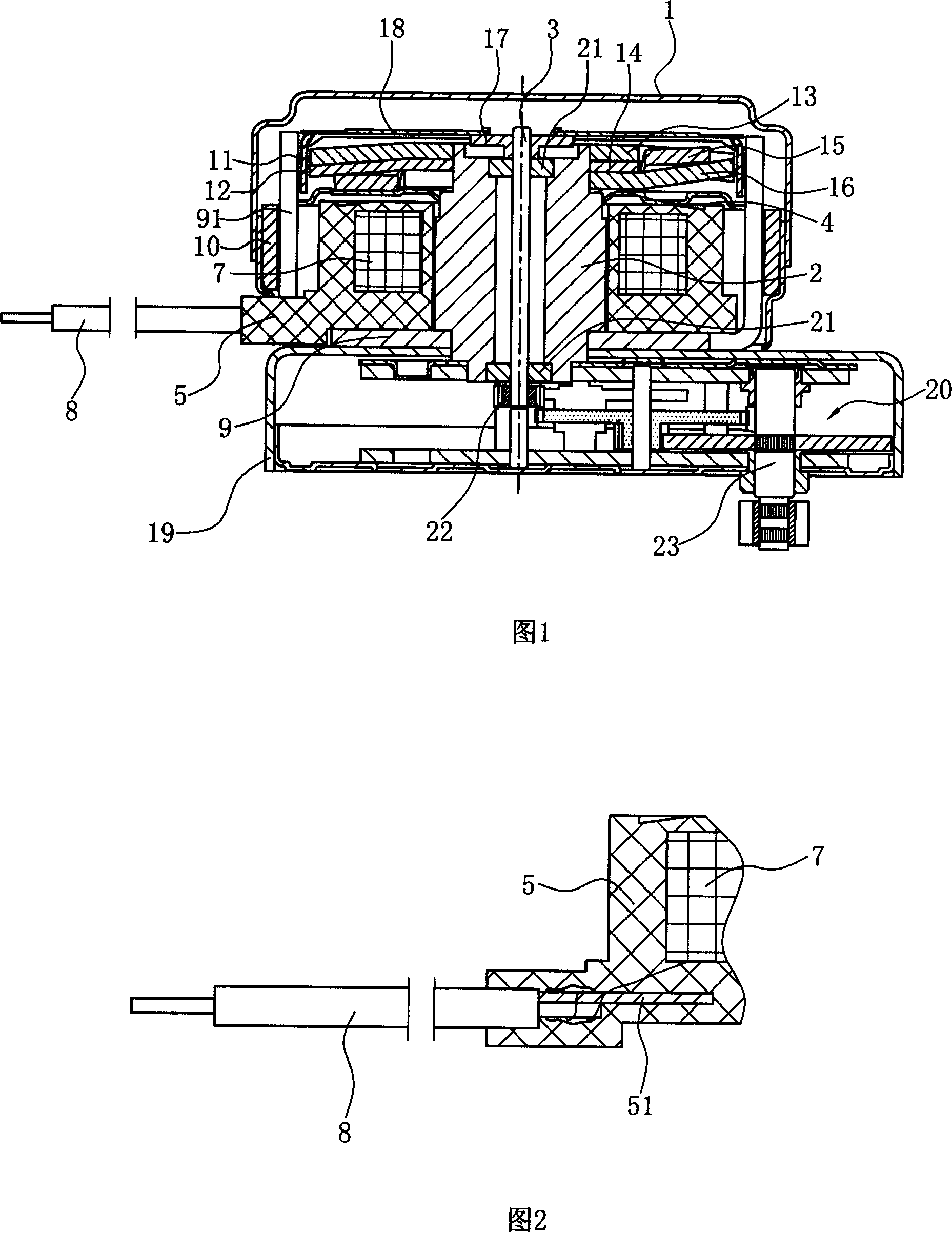
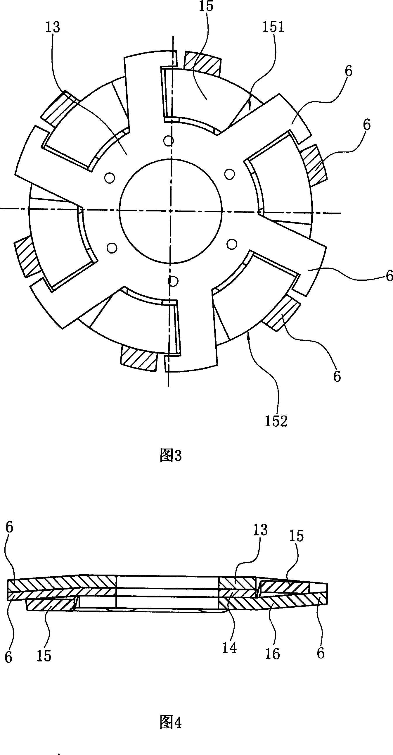
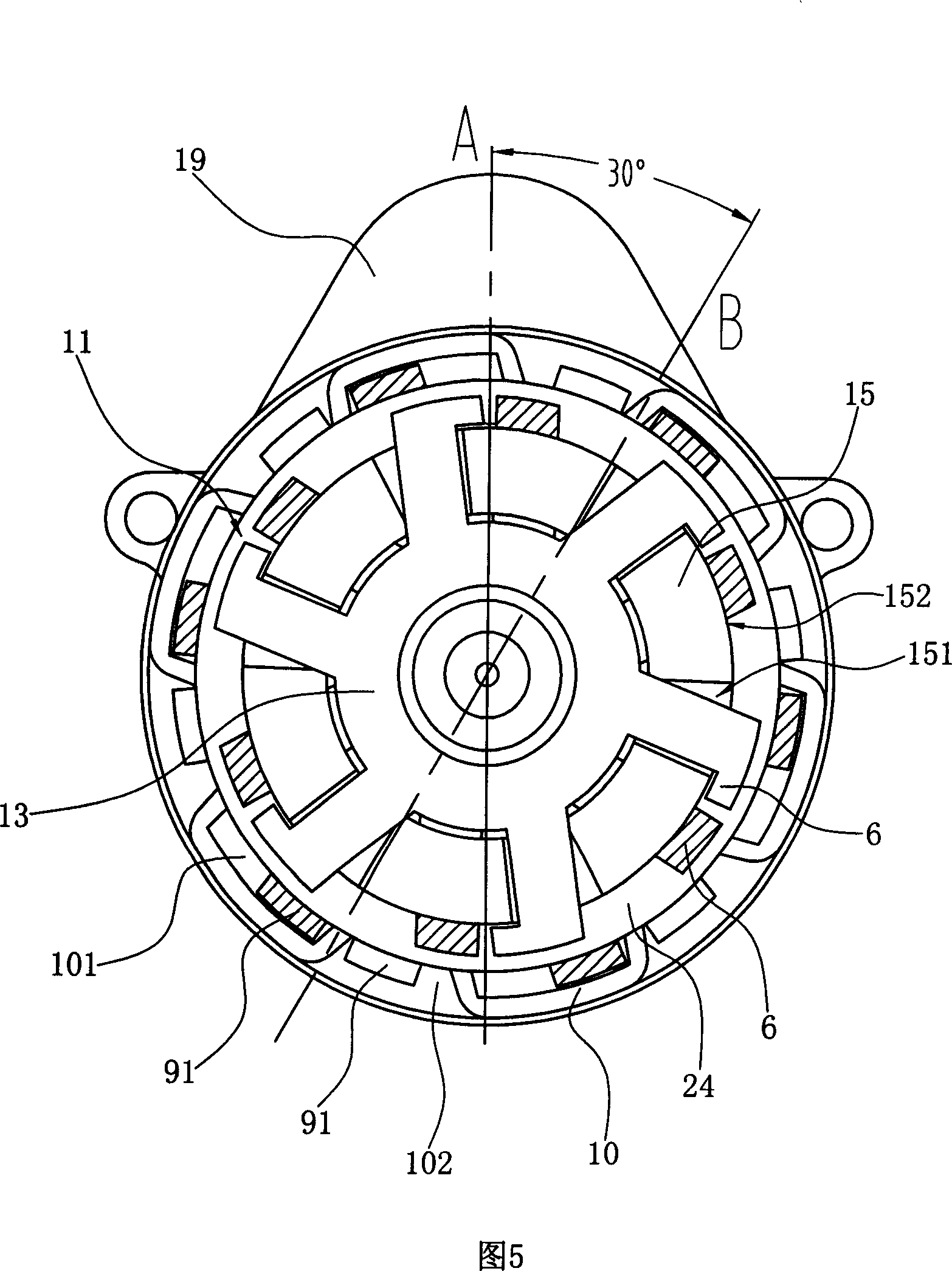
[0025] As shown in Figures 1 to 6, a hysteresis synchronous motor includes a housing 1. A gearbox base 19 is fixed at the lower part of the housing 1, and a gearbox assembly 20 is arranged in the gearbox base 19. The gearbox assembly 20 The gearbox component in the existing motor can be used, and the gearbox component is a gear transmission mechanism, which is a conventional technology, so it will not be elaborated;

[0026] The casing 1 is provided with an axially hollow iron core 2. The iron core 2 is made of electrical pure iron rods. A rotating shaft 3 passes through the iron core 2 through the bearings 21 arranged at the upper and lower ends of the iron core 2 and penetrates through it. Pass through the lower part of the casing 1 and enter the gearbox base 19, and connect with the gearbox assembly 20 through the head wheel 22 arranged on the rotating shaf...


PUM


Abstract

The invention relate to a magnet-lagging synchronized motor. An iron core is provided in a housing, and a rotating shaft passes through the iron core; a lower stator claw pole component with a plurality of lower claw poles is sheathed on the upper part of the iron core, and the adjacent lower claw poles are separated by a lower short-circuit ring to form a shading pole; a stator winding is sheathed in the middle of the iron core; an upper stator claw pole with a plurality of upper claw poles is sheathed on the lower part of the iron core, and an upper short-circuit ring is sheathed on the upper claw poles, the adjacent upper claw poles are separated by the upper short-circuit ring to form a shading pole, and an inner short-circuit ring is sheathed on the middle part of the iron core; annular clearances are formed between the lower stator claw pole component and the upper stator claw pole; and a rotor ring is positioned between the annular clearances. The process for manufacturing the motor comprises stamping, stress annealing, spot welding, bending, vacuum quenching, rivet pressing, welding, injection molding, encapsulating, and assembling. The inventive magnet-lagging synchronized motor has the advantages of novel and simple structure, convenient manufacturing, and low cost.

Description

technical field [0001] The invention relates to a hysteresis synchronous motor and its manufacturing process, in particular to a hysteresis synchronous motor suitable for occasions requiring frequent start and stop, momentary pause and constant torque. Background technique [0002] The hysteresis synchronous motor is a kind of AC motor. The rotor is a hysteresis rotor made of hysteresis material. The stator is slotted, and different forms of windings can be distributed in the slot according to needs. The rotation of the motor depends on the action of the rotating magnetic field of the stator, which makes the rotor generate hysteresis torque, starts the motor and pulls it into synchronous operation. Compared with other synchronous motors, the hysteresis motor has good starting performance. Generally, the power index of the hysteresis motor is not high, and its starting current is almost the same as the rated operating current. When the power supply voltage and load fluctuate,...

Claims


Application Information

Patent Timeline
IPC IPC(8): H02K19/08H02K19/10H02K15/02H02K15/00
Inventor 余国华
Owner 余国华
Why Eureka
Try Eureka