Holding member for fuel injection valve

A fuel injection valve and retaining component technology, applied in the directions of low pressure fuel injection, low pressure fuel injection, fuel injection device, etc., can solve problems such as damage to the reliability of the liquid tightness of the fuel injection valve, achieve easy loading and unloading, avoid deformation, The effect of preventing leakage

Inactive Publication Date: 2012-02-15
KEIHIN CORP
View PDF1 Cites 0 Cited by
  • Summary
  • Abstract
  • Description
  • Claims
  • Application Information

AI Technical Summary

Problems solved by technology

[0004] In the above-mentioned conventional holding member for a fuel injection valve, since the mounting boss is protrudingly provided on the outer peripheral surface corresponding to the fitting surface of the cover portion, during its molding, due to the influence of thermal shrinkage of the mounting boss portion, On the other hand, there is a possibility of deformation on the fitting surface of the cover part. If deformation occurs as described above, the reliability of the liquid-tightness of the fitting part where the fuel inlet part of the fuel injection valve and the cover part are fitted will be impaired.

Method used


Image

  • Holding member for fuel injection valve
  • Holding member for fuel injection valve
  • Holding member for fuel injection valve

Examples


Embodiment 1

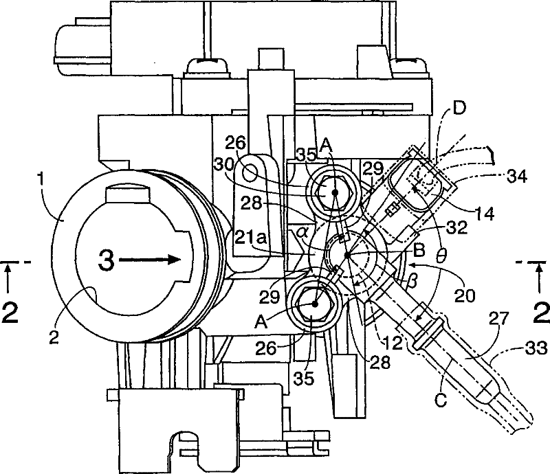
[0055] exist Figure 1 ~ Figure 3 Among them, the throttle valve body 1, which is an intake passage part of the engine, has an intake passage 2 connected to the intake port of the engine not shown in the figure, and opens and closes the intake passage 2 to adjust the intake air volume of the engine. The valve shaft 3 a of the butterfly throttle valve 3 is rotatably supported on the throttle body 1 . On the side wall of the throttle valve body 1 on the downstream side of the throttle valve 3, a mounting hole 4 and a mounting seat 5 are formed. The mounting hole 4 expands radially from the peripheral edge of the outer end.

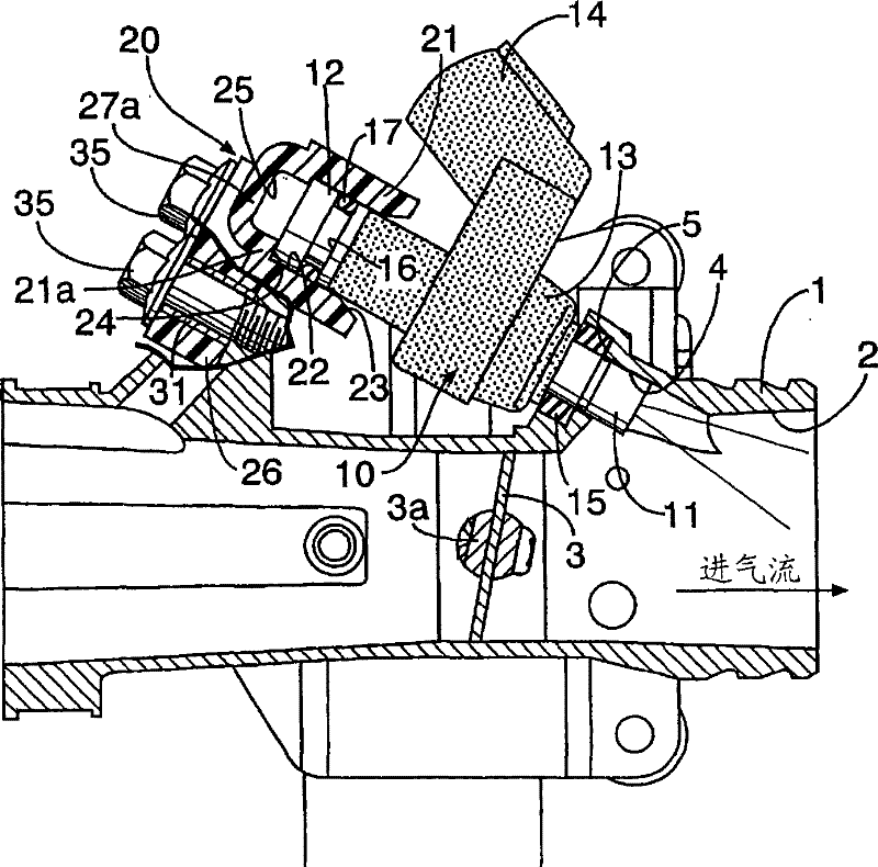
[0056] On the other hand, an electromagnetic fuel injection valve 10 mounted on the throttle body 1 has a fuel injection portion 11 at one end, and a fuel inlet portion 12 at the other end, and formed on the outer peripheries of their intermediate portions. The casing 13 made of synthetic resin is molded so as to embed the coil portion inside the package, ...

Embodiment 2

[0076] next to Figure 7 A second embodiment of the invention is shown for illustration.

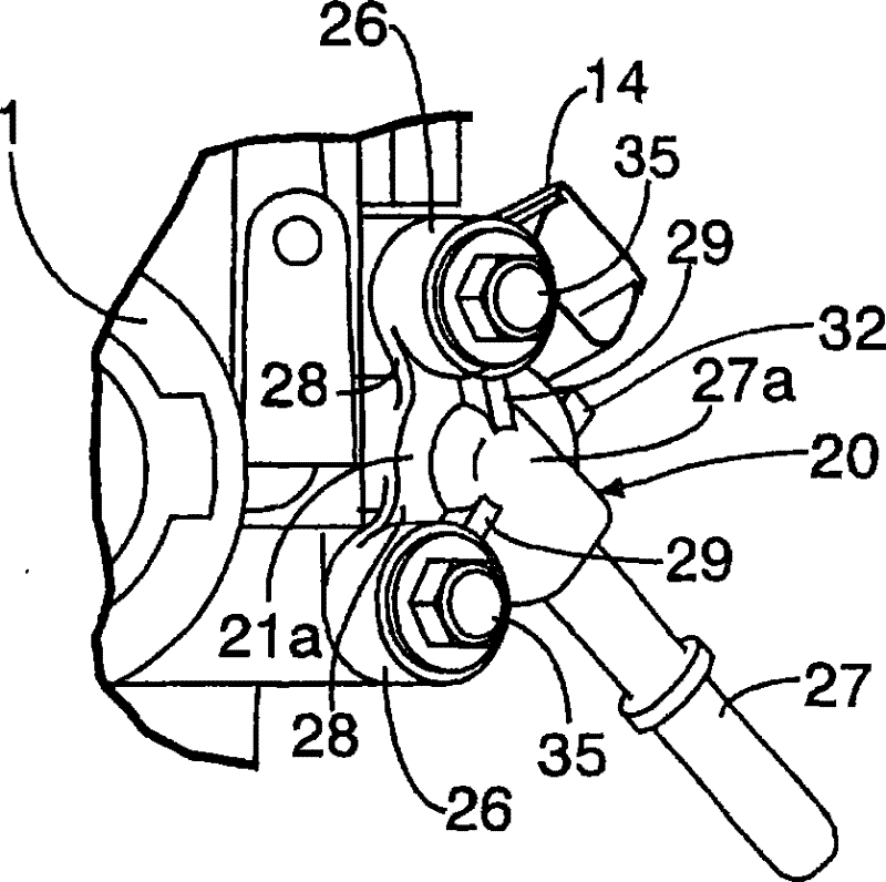
[0077] In the second embodiment, in the holding member 20 made of synthetic resin, on the peripheral edge of the opening of the guide surface 23 of the cover 21 , a pair of mounting protrusions are connected via a connecting portion 28 ′ whose thickness is thinner than that of the cover 21 . The platform parts 26, 26, and these mounting boss parts 26, 26 are arranged on the side of the cover part 21 with a small gap. The other structures are the same as those of the above-mentioned embodiment 1, so in the figure, the parts corresponding to the above-mentioned embodiment are marked with the same reference numerals, and repeated explanations are omitted.

[0078] In this second embodiment, even if the mounting bosses 26, 26 thermally shrink when the holding member 20 is molded with synthetic resin, the heat of the mounting bosses 26, 26 can be blocked by the thin connection portion 28'. Th...


PUM


Abstract

A holding member for a fuel injection valve capable of holding, on a throttle body (1), the fuel injection valve (10) formed by inserting a fuel injection part (11) at one end of the fuel injection valve into a mounting hole (4) formed in the throttle body. A fuel joint part (27) to which a fuel feed pipe (33) is connected is formed of a synthetic resin integrally with a mounting boss part (26) joined to the throttle body (1) so that the fuel joint part and the mounting boss part can be integrally connected to a cap part (21) fitted liquidtight to the outer periphery of a fuel inlet part (12) at the other end of the fuel injection valve (10). The mounting boss part (26) is connected to the cap part (21) to the inner periphery of the cap part (21) at a portion axially apart from the fitting surface (22) thereof to the fuel inlet part (12). Thus, since the heat shrinkage of the mounting boss part does not affect the inner peripheral surface of the cap part when the holding member for the fuel injection valve is molded, the liquid-tightness of the fitting part of the fuel inlet part to the cap part of the fuel injection valve can be secured.

Description

technical field [0001] The present invention relates to an improvement of a holding member for a fuel injection valve holding a fuel injection valve on an intake passage member into which a fuel injection portion at one end of the fuel injection valve is inserted. In the mounting hole provided, a single cover portion of the fuel injection valve holding member is fluid-tightly fitted on the outer periphery of the fuel inlet portion of the other end portion of the fuel injection valve so that the inner part and the inner part of the cover part are integrally connected around the cover part. The communicating fuel joint portion and the pair of mounting boss portions joined to the intake passage member are integrally molded from synthetic resin. Background technique [0002] The holding member for the above-mentioned fuel injection valve is known as disclosed in Patent Document 1 below. [0003] Patent Document 1: Japanese Patent Laid-Open No. 2002-54937 [0004] In the above-...

Claims


Application Information

Patent Timeline
Patent Type & Authority Patents(China)
IPC IPC(8): F02M69/00F02M55/02
Inventor 秋山裕茂藤野有辉后藤崇
Owner KEIHIN CORP
Why Eureka
Try Eureka