

Machine tool and method of correcting displacement of machine tool
A machine tool and displacement technology, applied in the field of thermal displacement, can solve problems such as increasing costs, and achieve the effects of improving machining accuracy, reliable thermal displacement, and reliable estimation
- Summary
- Abstract
- Description
- Claims
- Application Information
AI Technical Summary
Problems solved by technology
Method used
Image

Examples
Embodiment Construction
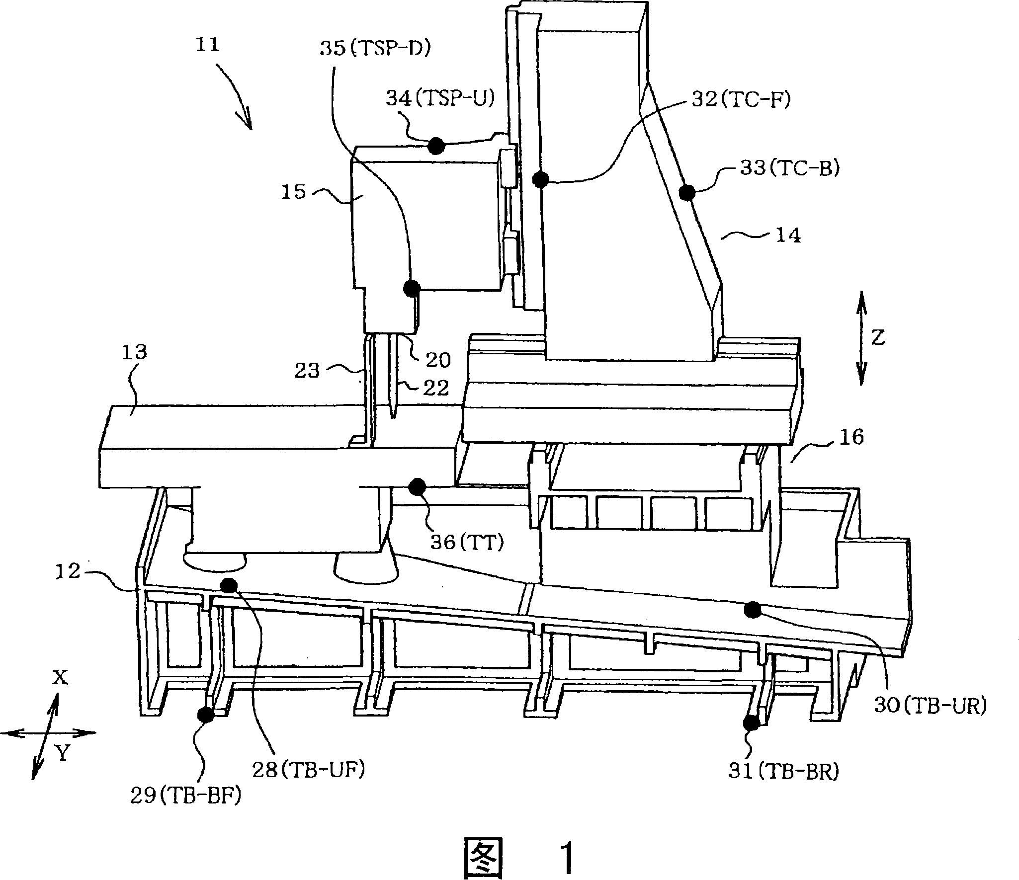
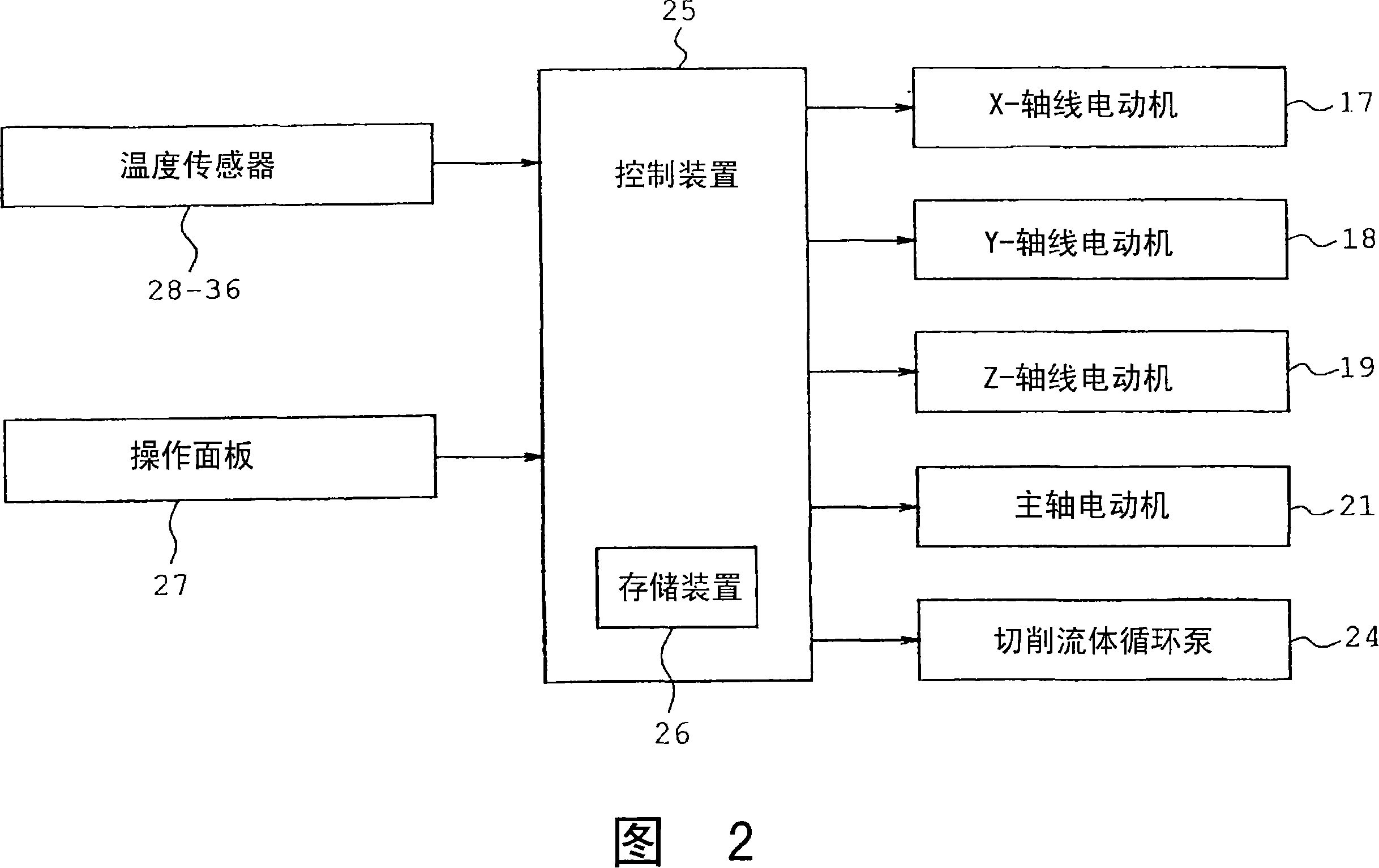
[0059] The present invention will be described in more detail with reference to the accompanying drawings. 1 to 18B show a first embodiment of the present invention. The machine tool according to this embodiment includes a machine tool body (machining center) 11 and a control device 25 (see FIG. 2 ) described later. Referring to FIG. 1 , the structure of the machine tool body 11 is schematically shown. In this embodiment, the X direction refers to the horizontal direction relative to the body 11 , the Y direction refers to the front-to-back direction, and the Z direction refers to the vertical direction. Each axis is controlled according to a three-dimensional (XYZ) coordinate system specific to the machine tool.
[0060] The body 11 of the machine tool includes a base 12, a table 13, a column 14, and a spindle head 15, each serving as a part, as shown in FIGS. 4A to 4E and 6 . The base 12 is installed, for example, on the floor of a factory. A table 13 is mounted on the f...
PUM
 Abstract
Description
Claims
Application Information