
Blade for wind-power generators

A generator and blade technology, which is applied to wind turbines, wind energy power generation, wind turbines in the same direction as the wind, etc., can solve problems such as increased cost and weakening of longitudinal internal reinforcement structures, and achieves the effect of eliminating risks.

Inactive Publication Date: 2008-03-26
GAMESA INNOVATION & TECH SA
View PDF2 Cites 17 Cited by
  • Summary
  • Abstract
  • Description
  • Claims
  • Application Information

AI Technical Summary

Problems solved by technology

Doing so would presumably increase the cost of the production process and reduce the wall portion of the longitudinal internal stiffening structure, with consequent weakening of said longitudinal internal stiffening structure

Method used


Image

  • Blade for wind-power generators
  • Blade for wind-power generators
  • Blade for wind-power generators

Examples


Embodiment Construction

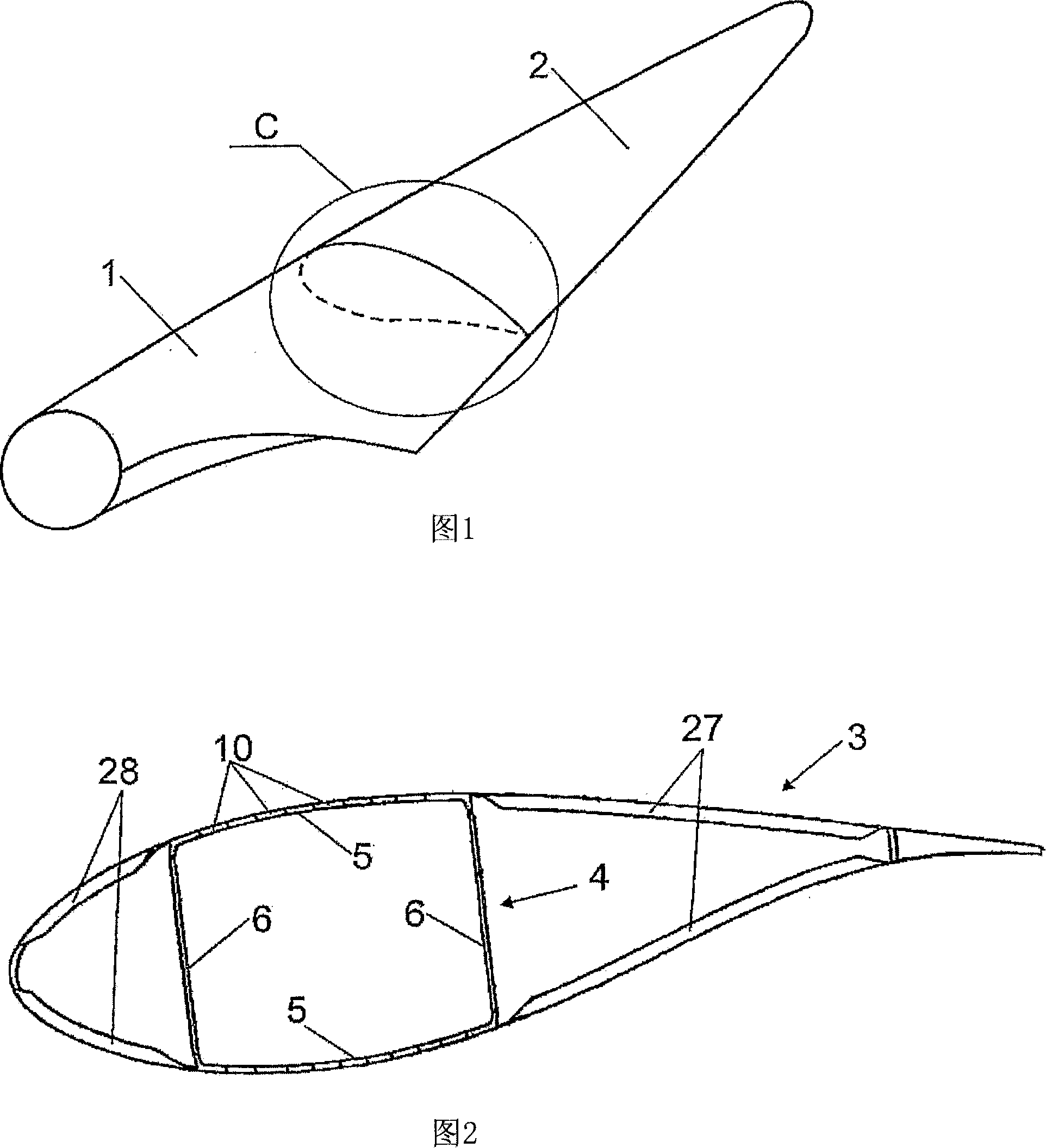
[0034] FIG. 1 shows a blade of a wind power generator of conventional configuration subdivided transversely into two parts, designated with reference numerals 1 and 2 . These parts have matching opposing locations, as shown in plan and perspective views in FIGS. 2 and 3 .

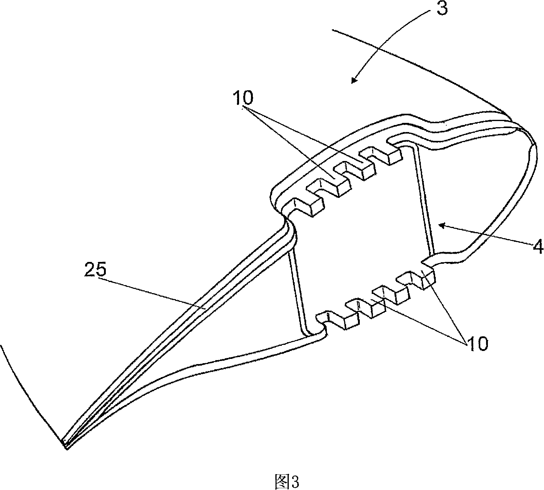
[0035] Each of sections 1 and 2 comprises an outer aerodynamic wall or shell, designated 3, and a longitudinal internal stiffening structure, designated 4, which in the example shown in the drawings The inner reinforcing structure is conceived as a box beam extending along said part, wherein said box beam has a wall 5 adjoining and forming part of the shell 3 and an intermediate wall 6 .

[0036] Parts 1 and 2 have connecting members at their opposite locations, said means being located at adjacent end locations of the longitudinal inner reinforcing structure 4 . Preferably, the aforementioned connection members are positioned to coincide with the wall portion 5 of the longitudinal internal reinforcement s...


PUM


Abstract

The invention relates to a blade for a wind generator. The inventive blade is divided transversely into two or more separate parts, each part comprising an aerodynamic skin or wall (3) and an internal longitudinal stiffening structure (4). In addition, the ends of the aforementioned sections are fitted with connection members comprising metal inserts (10) axially housed and fixed inside the walls of the inner longitudinal reinforcement structure.

Description

technical field [0001] The invention relates to a blade for a wind power generator, which is subdivided transversely into two or more separate parts, each of said separate parts comprising a solid longitudinal structure and an aerodynamic outer wall part or housing, the opposite ends of which are fitted with connection members. Background technique [0002] Today's wind turbines are designed to capture higher levels of power. Among the components that contribute to the power of a wind turbine are the blades including the rotor. The aerodynamic properties and size of the blades are fundamental aspects for increasing the power of a wind turbine. For this reason, longer blades are produced today. [0003] Since wind turbines are usually set up in inaccessible places, the transportation of the blades often poses a great problem, especially due to the length of the blades. In order to solve this problem, the technique of laterally subdividing the blade into two or more separa...

Claims


Application Information

Patent Timeline
IPC IPC(8): F03D1/06
CPCF05B2280/6003F05B2250/182F03D1/0675F05C2253/04Y02E10/721F05B2230/60F05B2240/302Y02E10/72Y02P70/50F03D1/065
Inventor 何塞·伊格纳西奥·略伦特·冈萨雷斯塞尔希奥·贝莱斯·奥里亚
Owner GAMESA INNOVATION & TECH SA
Features
  • Generate Ideas
  • Intellectual Property
  • Life Sciences
  • Materials
  • Tech Scout
  • Unparalleled Data Quality
  • Higher Quality Content
  • 60% Fewer Hallucinations
Learn More