Home care apparatus monitor system

A home care and monitoring system technology, applied in nursing facilities, medical equipment, hospital equipment, etc., can solve the problems of users’ daily life inconvenience, inability to correctly grasp user’s physical information, and inability to detect faults early

Inactive Publication Date: 2008-03-26
MITSUBA CORP +1
View PDF5 Cites 15 Cited by
  • Summary
  • Abstract
  • Description
  • Claims
  • Application Information

AI Technical Summary

Problems solved by technology

In contrast, in the above-mentioned remote monitoring system, the point of view only focuses on the life of the monitored object, but does not consider the support to the nursing staff such as the height of the bed at the time of nursing.
[0014] In addition, for various home care equipment such as electric beds and electric wheelchairs, it is difficult to know when the user wears and uses them, and it is impossible to accurately grasp the user's own physical information.
For example, when the user suffers from some disease or frequently uses home care equipment while sleeping, it is difficult to judge whether the user is healthy just by checking the driving status of the equipment, so it is considered that the disease will be discovered later
[0015] On the other hand, since the user cannot perform the desired operation through the use environment when there is any fault in the living space, the fault is not known until the user visits the home, so the fault cannot be detected early, which will cause a serious problem for the user. inconvenience to daily life
In addition, in the existing home care equipment, the operation of confirming the corresponding relationship between the operating state and the driving state of the equipment must be carried out on site, and the monitoring and management personnel cannot find the fault of the equipment before arriving at the scene, which will cause the problem of late detection of the fault

Method used


Image

  • Home care apparatus monitor system
  • Home care apparatus monitor system
  • Home care apparatus monitor system

Examples


Embodiment 2

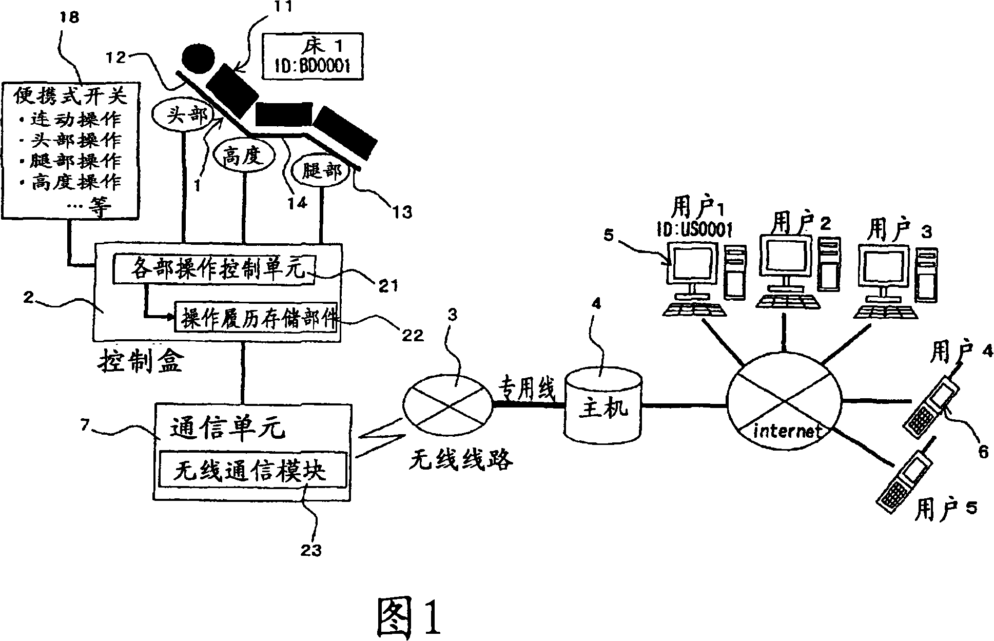
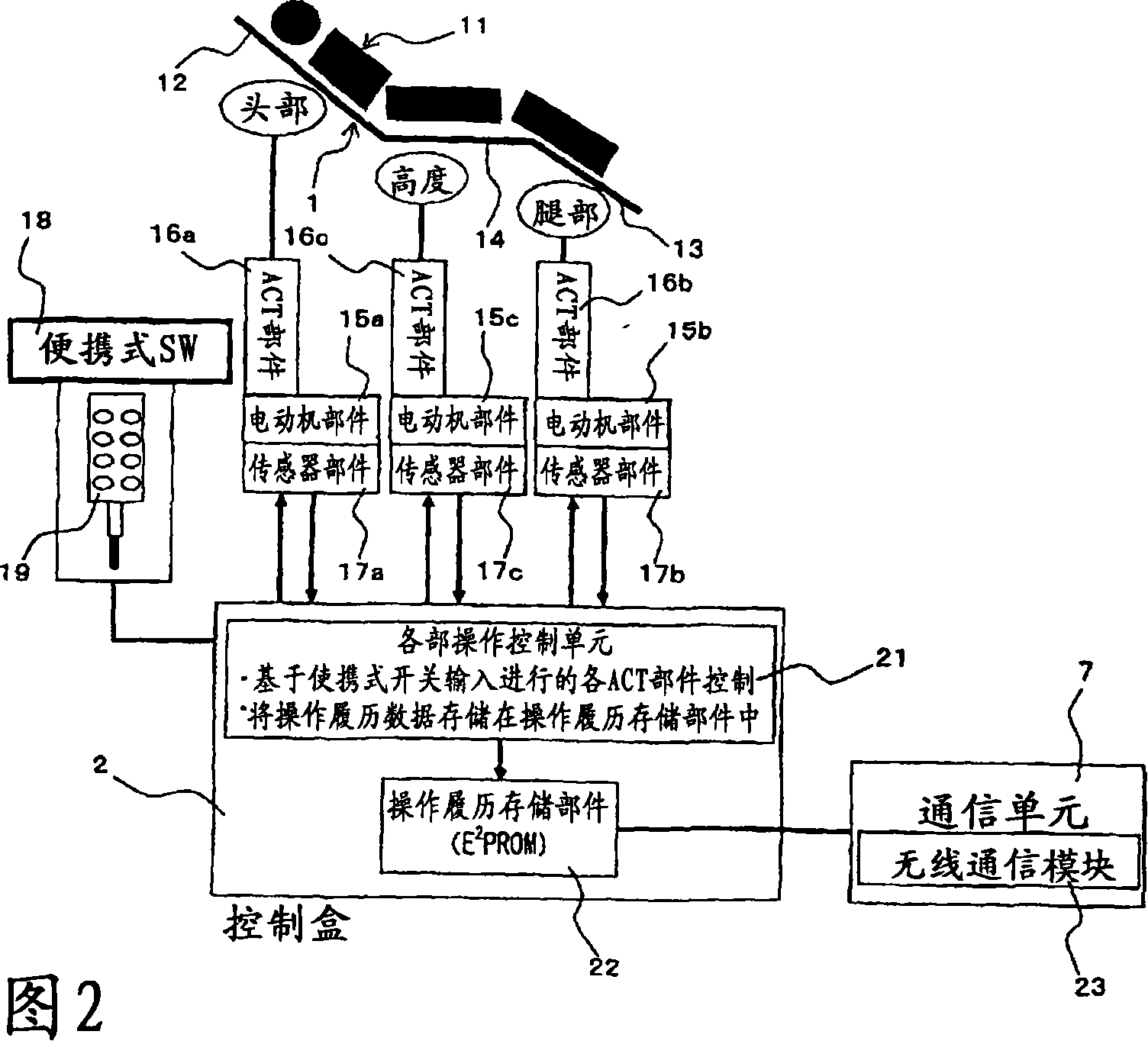
[0115] Next, as a second embodiment of the present invention, a home care facility monitoring system targeting electric wheelchairs will be described. FIG. 11 is a block diagram showing the system configuration of the electric wheelchair. In addition, the same code|symbol is attached|subjected to the same part as Example 1, and the description is abbreviate|omitted. 1 , this system stores operation history information of an electric wheelchair (home care equipment; hereinafter simply referred to as a wheelchair) 41 in a control box 42 and transmits the operation history information to the host computer 4 via the wireless line 3 .

[0116] Left and right drive wheels (drive members) 43a, 43b are provided on the wheelchair 41 . The drive wheels 43a, 43b are provided with motor means (electric drive means) 44a, 44b using electric motors, respectively. Sensor members 45a, 45b (sensor units) for detecting the operating state of the motor members 44a, 44b are attached. Sensor mem...


PUM


Abstract

In a bed (home care equipment) 1, based on the switch operation, respective drive units of a head unit 12, a leg unit 13, and a height adjustment unit 14 are actuated by motor units 15a to 15c and actuator units 16a to 16c. The actuation state of the respective drive units are detected by the sensor units 17a to 17c, and a respective-unit-operation control means 21 figures out the actuation state of the drive units based on a detection signal, and stores the performance history of the drive units in the operation history storage unit 22 as operation history information. The operation history information in the operation history storage unit 22 is transmitted to a host computer 4 by a communication unit 7. The host computer 4 processes the received operation history information to data which can be displayed by the animation display, graph display, and accumulated time period display, and transmits thus processed data to a computer 5 etc. which is connected to the host computer 4 through the Internet line.

Description

technical field [0001] The present invention relates to a home care equipment monitoring system for grasping the life information of care needers and support needers, etc., and constructing the most comfortable living environment for care needers, and particularly relates to a home care equipment monitoring system based on electric beds and electric wheelchairs, etc. A system that acquires life information of care-seekers, etc., based on their usage status. Background technique [0002] In recent years, with the establishment of the nursing care insurance system, qualified guardians will be assigned to guardianship objects who need care and support in daily life, such as the elderly, the physically disabled, and patients with intractable diseases. The management personnel make individual guardianship plans suitable for each guardianship object, etc. When making a guardianship plan, guardianship administrators and medical related personnel visit their own guardianship subjec...

Claims


Application Information

Patent Timeline
Patent Type & Authority Applications(China)
IPC IPC(8): G06Q50/00H04Q9/00A61G5/00A61G5/04A61G12/00A61G7/05A61B5/00A61G7/00G16H40/63G16H40/67
CPCA61G5/04A61G5/10A61G7/018G06F19/3418A61G2203/14G06Q50/22G16H40/67G16H40/63
Inventor 稻叶光则川越邦亮长濑裕一长冈浩下川真人松宫梨香
Owner MITSUBA CORP
Why Eureka
Try Eureka