Shaft sealing

A shaft seal and seal ring technology, applied in the field of vacuum pumps, can solve the problems of shaft seal damage, escape, failure, etc., and achieve the effect of good sealing characteristics

Inactive Publication Date: 2008-04-02
LEYBOLD HERAEUS GMBH & CO KG
View PDF1 Cites 14 Cited by
  • Summary
  • Abstract
  • Description
  • Claims
  • Application Information

AI Technical Summary

Problems solved by technology

[0003] In such shaft seals, aggressive media, especially moisture, can come into contact with the piston rings and cause damage or even failure of the shaft seal
In addition, toxic or explosive gases can escape from the separation chamber

Method used


Image

  • Shaft sealing
  • Shaft sealing
  • Shaft sealing

Examples


Embodiment Construction

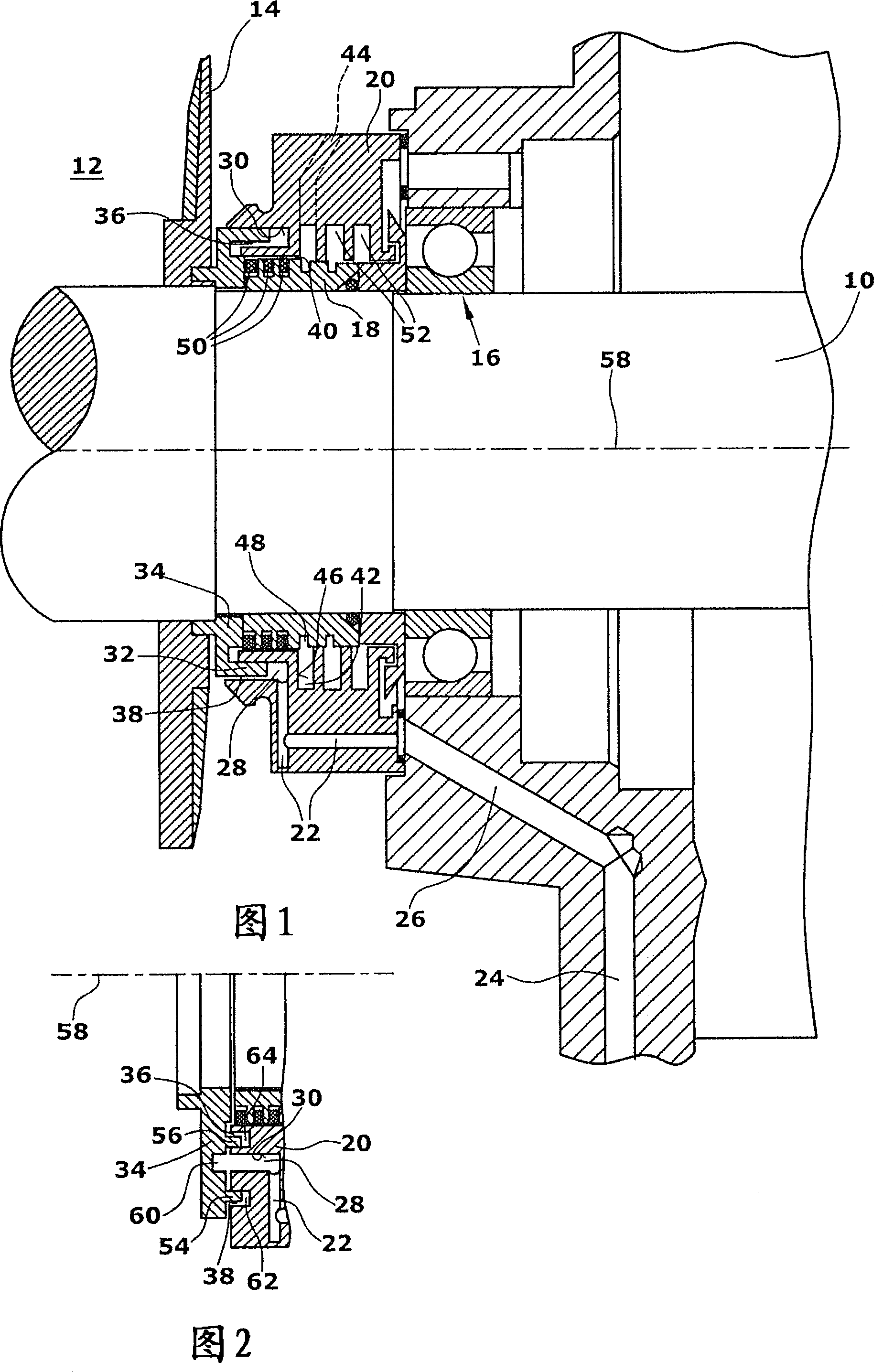
[0025] The rotor shaft 10 is connected on the suction chamber side or dry side 12 to a rotor 14 , in order to simplify the illustration, only one rotor blade of a rotor designed as a helical rotor is shown. Furthermore, the rotor shaft 10 is connected to a bearing 16 , which in the embodiment shown is a ball bearing. Bearing 16 is lubricated with oil, for example. A shaft seal according to the invention is arranged between the rotor 14 and the bearing 16 .

[0026] In a first embodiment ( FIG. 1 ), the shaft seal comprises an inner sealing ring 18 permanently connected to the rotor shaft 10 . The inner sealing ring 18 is surrounded by an outer sealing ring 20 which is arranged, for example permanently, in a housing, not shown. A supply channel 22 is provided in the outer sealing ring 20 , which is connected to a channel 26 provided in the housing 24 . Via channel 26 and supply channel 22 sealing gas may be supplied to sealing gas chamber 28 .

[0027] In the embodiment sho...


PUM


Abstract

Disclosed is a shaft seal which is suitable especially for vacuum pumps such as propeller pumps. Said shaft seal comprises an inner sealing ring (18) that can be connected to the shaft, and an outer sealing ring (20) which surrounds the inner sealing ring (18). A circumferential groove (30) into which buffer gas can be introduced via a feeding duct (22) is provided in the outer sealing ring (20). A buffer gas disk (34) that is fitted with an attachment (32) which extends into the groove (30) can also be connected to the shaft (10), whereby a buffer gas chamber (28) is embodied in the groove (30). Said buffer gas chamber (28) is joined to a sealing gap (40) located between the inner and the outer sealing ring (18, 20) via a chamber gap (36) which the buffer gas can penetrate. A separation chamber (42) which is formed by the inner and the outer sealing ring (18, 20) and is connected to a discharge duct (44) in order to evacuate buffer gas adjoins the sealing gap (40).

Description

technical field [0001] The invention relates to a shaft seal particularly suitable for vacuum pumps such as screw pumps. Background technique [0002] A shaft seal for a screw pump is described in DE10207929. Screw pumps generally comprise two rotor shafts, which are connected to the rotor in respective rotor parts. Furthermore, the shaft is connected to bearings, which are usually lubricated with oil. A shaft seal is provided between the bearing and the rotor part. Especially when a vacuum is created, the need for seals is increased since oil or other lubricants must be prevented from flowing from the bearing side to the rotor side. DE10207929 proposes the combination of an oil seal arranged on the bearing side and an air seal arranged on the rotor side. In this case, the gas seal is designed as a labyrinth seal combined with a plurality of piston rings. A radially extending separation chamber is defined between the air seal and the oil seal, and the separation chamber...

Claims


Application Information

Patent Timeline
Patent Type & Authority Applications(China)
IPC IPC(8): F16J15/447F04C27/00
CPCF04D29/104F04C18/16F04C27/009F16J15/406F04C27/00F16J15/447
Inventor 托马斯·德赖费特沃尔夫冈·吉贝曼斯伯恩哈德·克利姆海因茨·托伦
Owner LEYBOLD HERAEUS GMBH & CO KG
Why Eureka
Try Eureka