
Eureka
For R&D, Eureka makes reading and utilizing patents & technical documents easy.
Eureka AIR
Designed for self-driven R&D workflows. Generate viable solutions, solve complex R&D challenges, empower your innovation with AI.

Eureka Materials
Designed for material experts only. Revolutionize your material R&D, from search, analyze, to developing new materials.

TechResearch
Generate reliable direction feasibility study reports for your R&D in just a few steps.

TechSeek
Discover and master advanced knowledge NOW. Basics, ideas, possibilities, all at once.

TechMind
As an expert in R&D Theories, TechMind can generates customized viable solutions instantly.

TechRisk
Analyze your overall solution with one click, know your potential R&D risks in advance.

TechMonitor
Get weekly tech updates, stay abreast of the latest tech innovations and key insights.
Cavity mould component
A cavity mold and component technology, which is applied in the field preparation of formwork/formwork/work frame, building components, building construction, etc., can solve the problems of low production efficiency, inconvenient assembly line production, inconvenient production, etc.
- Summary
- Abstract
- Description
- Claims
- Application Information
AI Technical Summary
Problems solved by technology
Method used
Image

Examples
Embodiment Construction
[0061] The present invention will be further described below in conjunction with the accompanying drawings and embodiments.
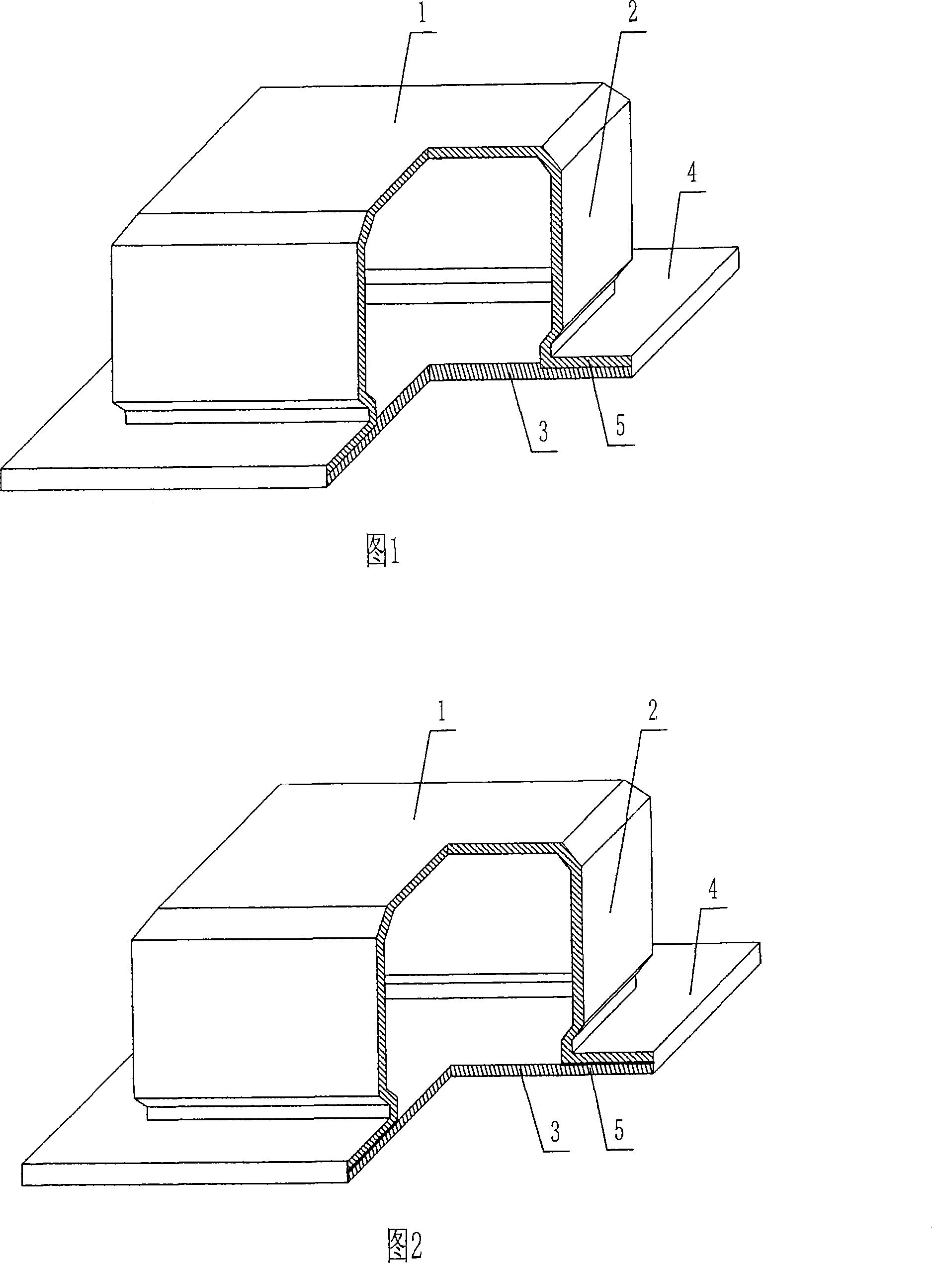
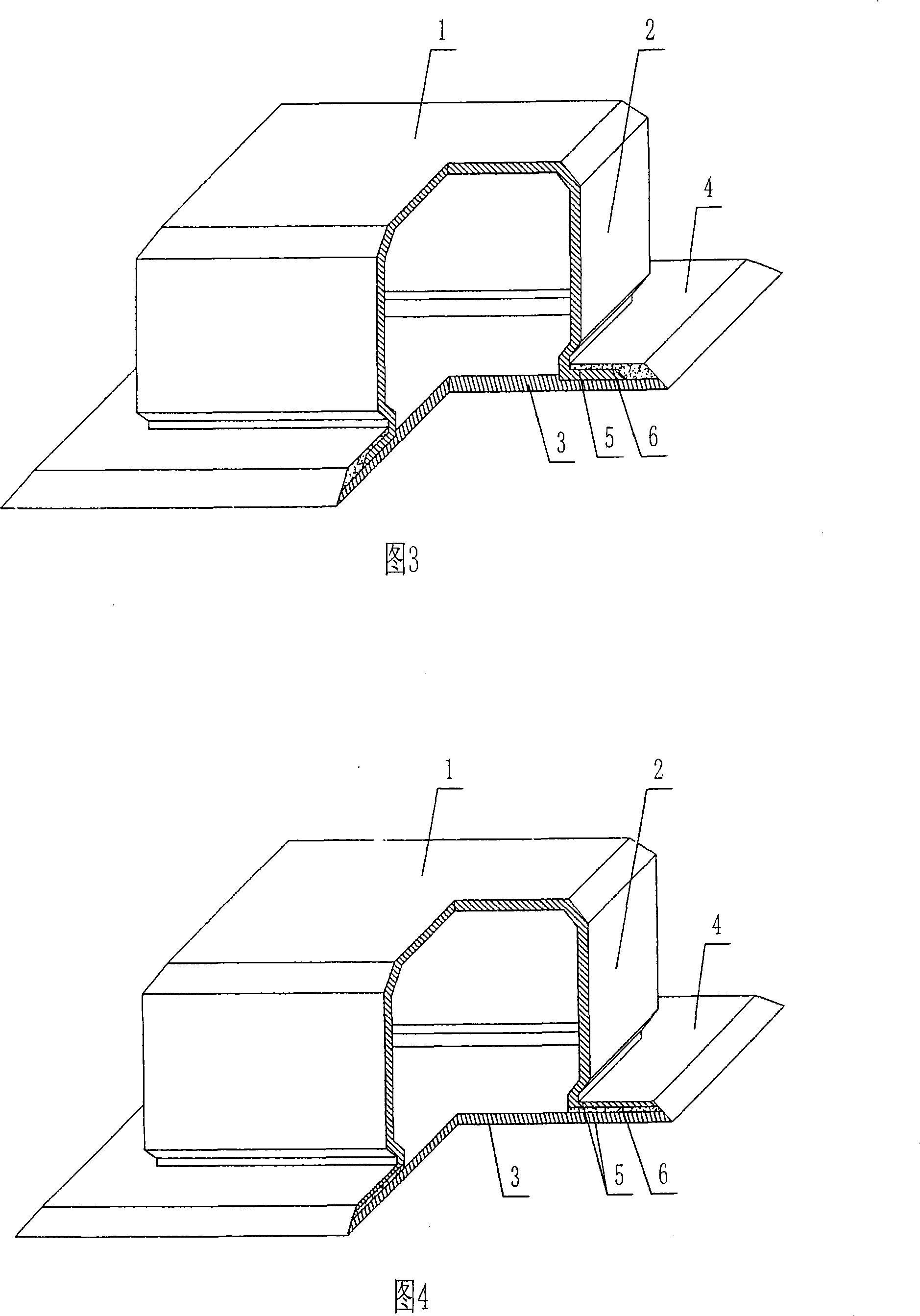
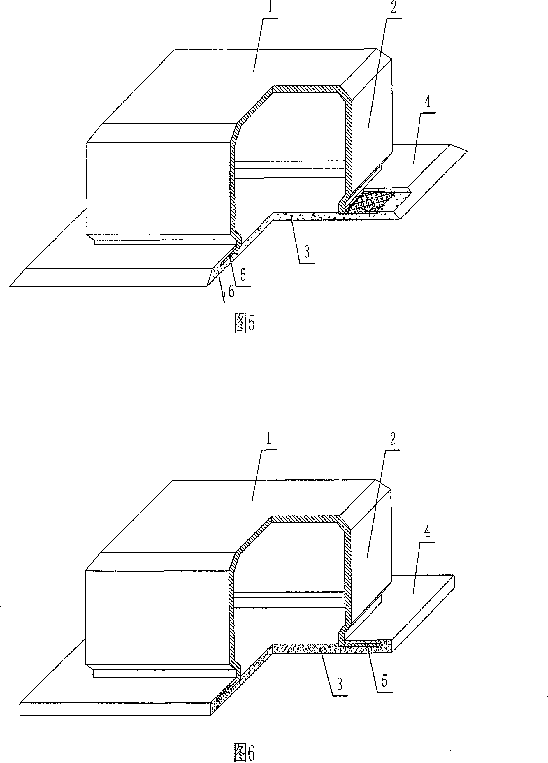
[0062] As shown in the accompanying drawings, the present invention includes an upper plate 1, surrounding side walls 2, lower bottom plate 3, and raised edges 4, the upper plate 1, surrounding side walls 2, and lower bottom plate 3 form a closed cavity, and the prefabricated surrounding side walls 2 It is characterized in that at least one side flange 4 is a laminated layer flange, and the laminated layer flange includes at least one prefabricated layer 5. In each accompanying drawing, 1 is an upper plate, 2 is a surrounding side wall, 3 is a lower bottom plate, 4 is an overhang, and 5 is a prefabricated layer. In the following drawings, those with the same number have the same description. As shown in Figure 1, the upper plate 1, the surrounding side walls 2 and the lower base plate 3 form a closed cavity, and the raised edge 4 protrudes from the peri...
PUM
 Abstract
Description
Claims
Application Information
 - R&D Engineer
- R&D Manager
- IP Professional
- Industry Leading Data Capabilities
- Powerful AI technology
- Patent DNA Extraction
Browse by: Latest US Patents, China's latest patents, Technical Efficacy Thesaurus, Application Domain, Technology Topic, Popular Technical Reports.
© 2024 PatSnap. All rights reserved.Legal|Privacy policy|Modern Slavery Act Transparency Statement|Sitemap|About US| Contact US: help@patsnap.com