
Directly-down backlight module and blooming piece fixed structure thereof

A technology of optical diaphragm and backlight module, which is applied in optics, nonlinear optics, instruments, etc., can solve problems such as warping and deformation, residual stress of optical diaphragm, etc., and achieve the goal of preventing warping and deformation, improving display quality and optical taste Effect

Inactive Publication Date: 2008-04-09
CHUNGHWA PICTURE TUBES LTD
View PDF0 Cites 18 Cited by
  • Summary
  • Abstract
  • Description
  • Claims
  • Application Information

AI Technical Summary

Problems solved by technology

[0008] In order to solve the problem that the optical film of the backlight module in the prior art is warped due to residual stress caused by changes in temperature and humidity, one of the purposes of the present invention is to provide a fixing structure for the optical film of the backlight module with outward tension to maintain Flattening of Optical Films

Method used


Image

  • Directly-down backlight module and blooming piece fixed structure thereof
  • Directly-down backlight module and blooming piece fixed structure thereof
  • Directly-down backlight module and blooming piece fixed structure thereof

Examples


Embodiment Construction

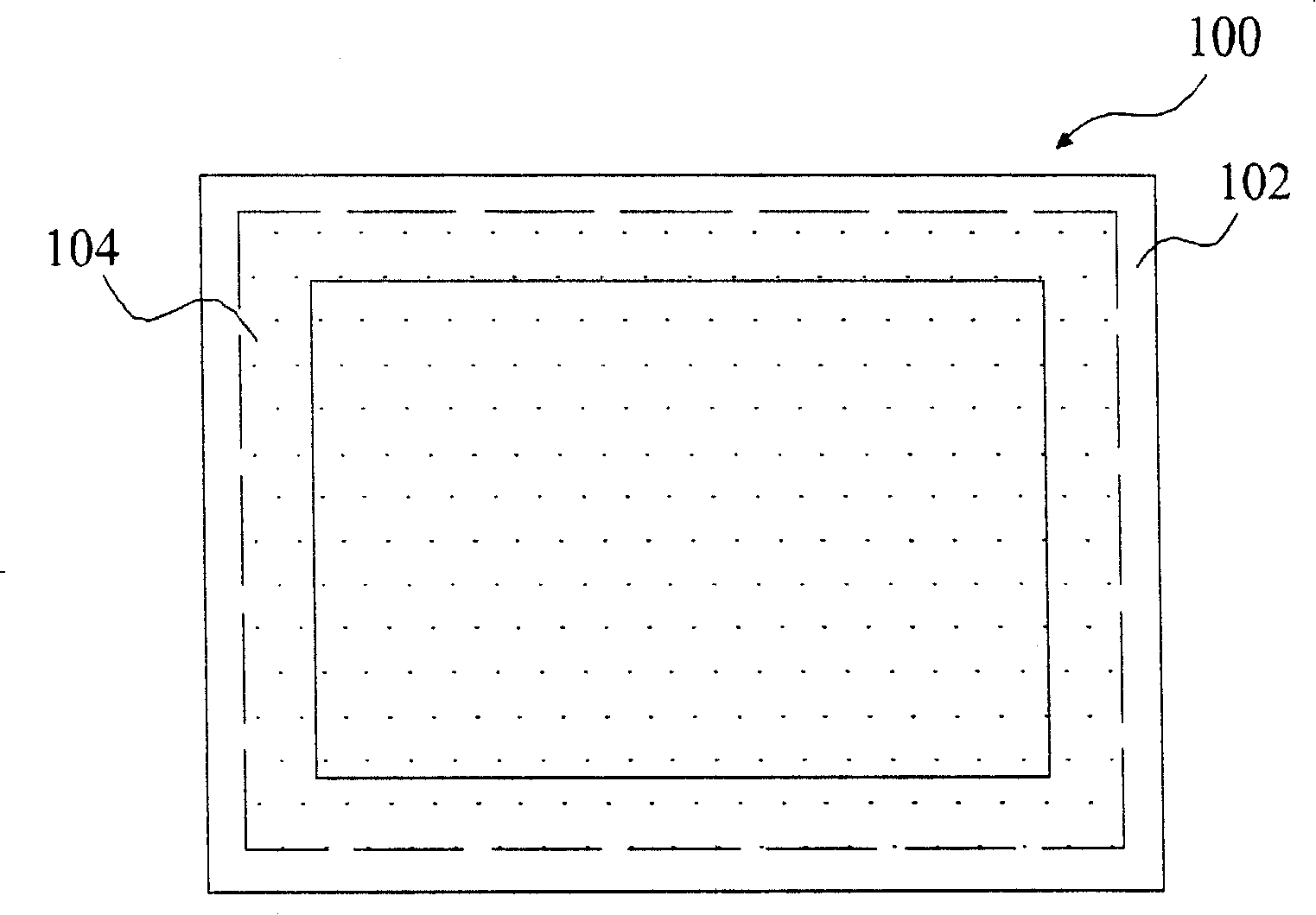
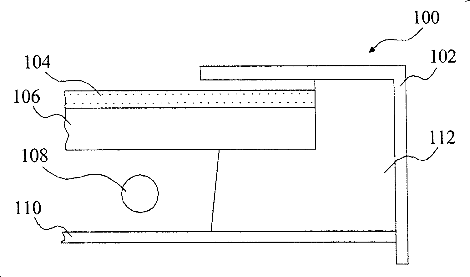
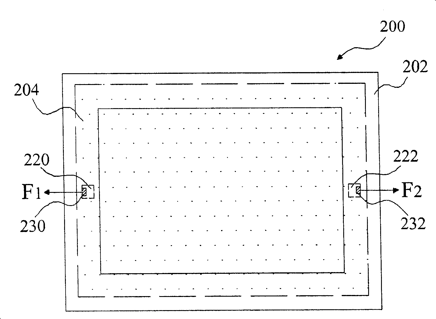
[0025] Figure 2A It is a schematic top view of a direct-type backlight module 200 according to an embodiment of the present invention. The optical film group 204 of the direct-type backlight module 200 is placed under the outer frame 202. The optical film group 204 includes at least one optical film. The frame 202 surrounds and covers the edge of the optical film set 204 , and the part of the optical film set 204 not covered by the outer frame 202 is the display area of ​​the display. The left and right edges of the optical film group 200 located in the non-display area respectively have through holes 220, 222, and two elastic bodies 230, 232 are respectively placed in the through holes 220, 222 and against the edges of the through holes to provide two outward tensions. f 1 , F 2 Given the optical film group 204, the outward tension F 1 with F 2 The optical film group 204 will be maintained flat, and will not be warped due to changes in the temperature and humidity of the...


PUM


Abstract

A down-backlight module and an optical film fixed structure comprises at least one of the optical films, two non-neighboring edges of the optical film group are provided with at least one through hole, each through hole is symmetrically or asymmetrically arranged with the through hole of one non-neighboring edge, a plurality of flexible bodies are respectively arranged in each through hole and respectively provide an outward tension so as to maintain the optical film group flat, so the warpage distortion is not produced due to the changing of the environment temperature and humidity, the display quality and the optical taste of the plane display is effectively improved.

Description

【Technical field】 [0001] The invention relates to a fixing structure of an optical film of a backlight module, and in particular provides an optical film fixing structure capable of preventing warping and deformation of the optical film. 【Background technique】 [0002] Thin Film Transistor-Liquid Crystal Display (TFT-LCD) has the advantages of low power consumption, thin shape, light weight, and low voltage drive, so it is currently one of the most common flat-panel displays and is widely used in notebook computers , Desktop computers and LCD TVs and other electronic products. [0003] Usually, a thin film transistor liquid crystal display panel (Panel) is composed of a thin film transistor (Thin Film Transistor, TFT) array substrate and a color filter (Color Filter, CF) substrate, and a liquid crystal layer is filled on the TFT array substrate and CF substrate. Because TFT-LCD cannot emit light by itself, the source light for image display needs to be provided by the ligh...

Claims


Application Information

Patent Timeline
Patent Type & Authority Applications(China)
IPC IPC(8): G02F1/1335G02F1/13357G02F1/1333
Inventor 林琪升林文郁谢忠志
Owner CHUNGHWA PICTURE TUBES LTD
Learn More