
Display device

A technology for a display device and a display panel, which can be applied to identification devices, instruments, etc., can solve the problems of display panel deformation, image quality deterioration, etc., and achieve the effect of easy positioning

Inactive Publication Date: 2008-04-09
SEIKO EPSON CORP
View PDF1 Cites 15 Cited by
  • Summary
  • Abstract
  • Description
  • Claims
  • Application Information

AI Technical Summary

Problems solved by technology

However, in this case, since the restoring force of the display panel deformed into a ring shape is suppressed by the rails provided on the entire circumference of the frame, the display panel is likely to be deformed, which may degrade the image quality.

Method used


Image

  • Display device
  • Display device
  • Display device

Examples


no. 1 approach

[0076] [1. Overall structure]

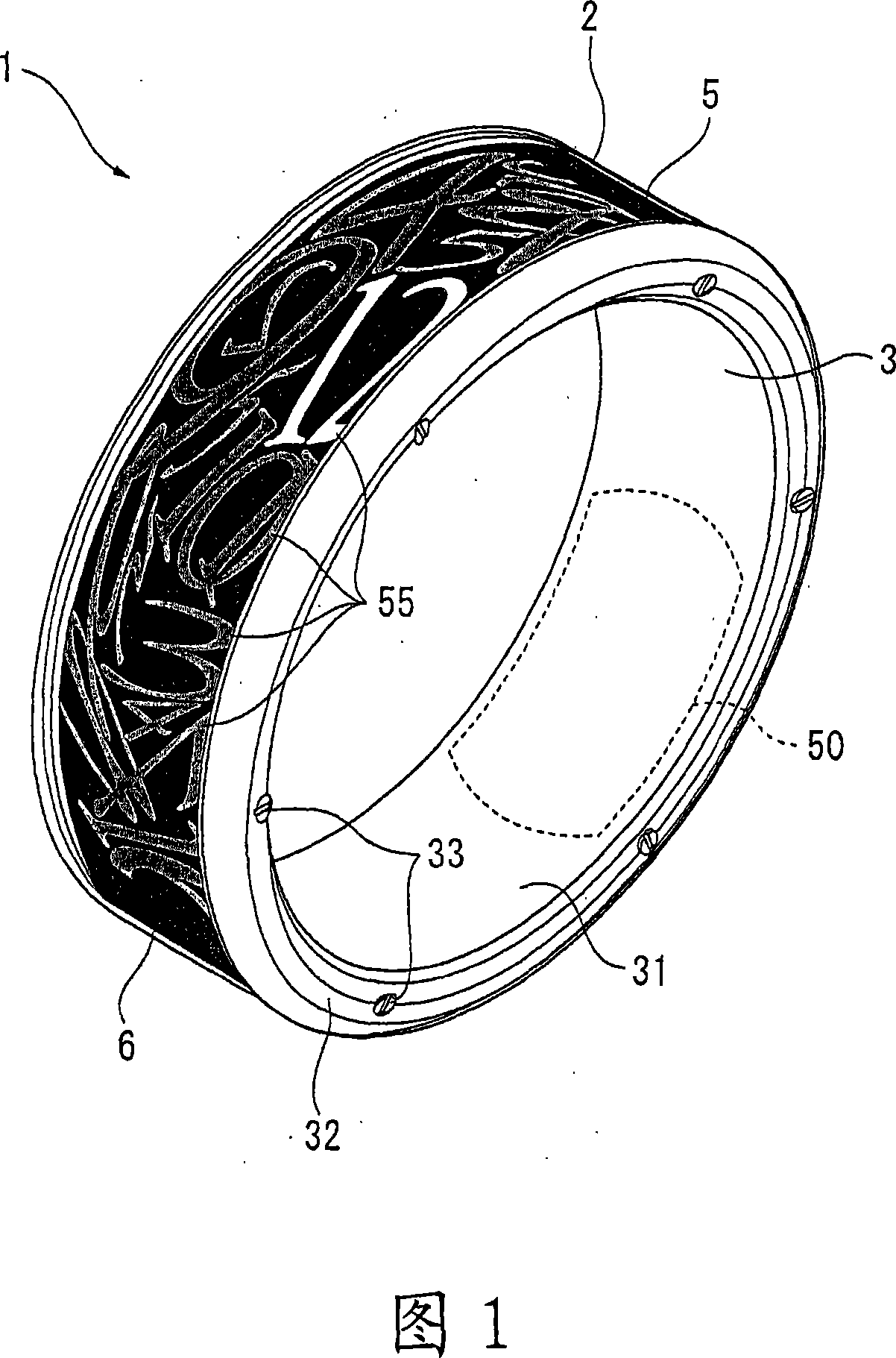
[0077] FIG. 1 is a perspective view of a wristwatch 1 according to the present embodiment.

[0078] As shown in FIG. 1 , a wristwatch 1 as a display device according to the present embodiment is formed in a cylindrical shape and is a bracelet-shaped wristwatch worn on the wrist. On the outer peripheral surface of the wristwatch 1, electrophoretic display panels 5 for displaying the time and date are arranged substantially on the entire circumference.

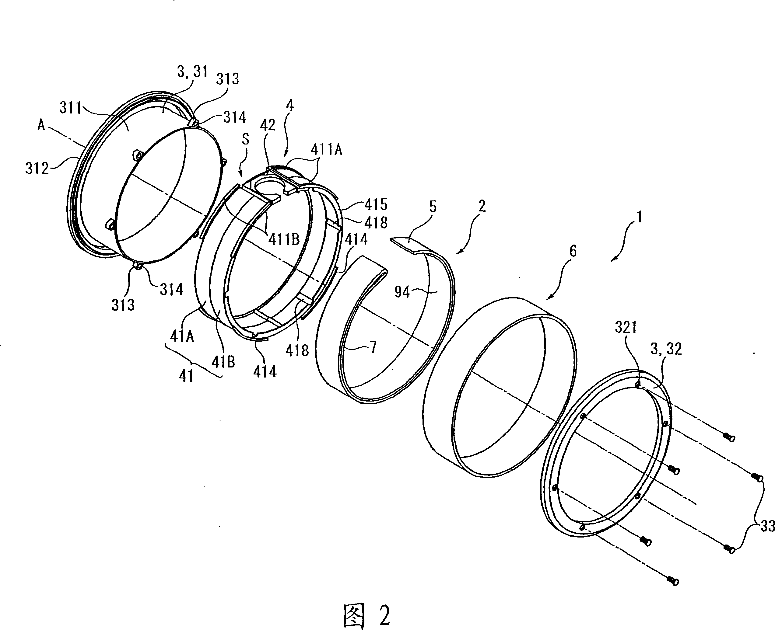
[0079] FIG. 2 is an exploded perspective view of the wrist watch 1 .

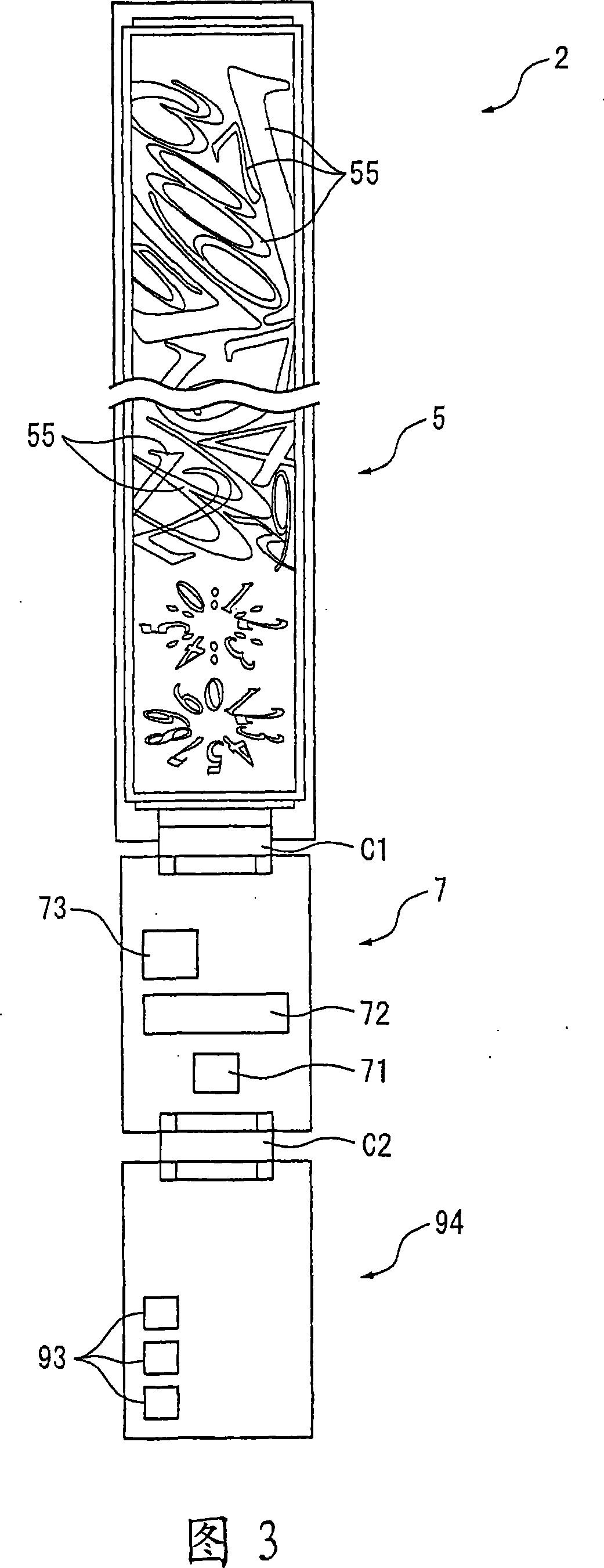
[0080] As shown in FIG. 2 , the wristwatch 1 is configured to have: a substantially cylindrical frame 3; a substantially cylindrical middle frame 4 fitted on the frame 3; a display module 2 mounted on the middle frame 4; The cover glass 6 of the light-transmitting member. The middle frame 4 has a display panel 5 and a switch substrate 94 . The display panel 5 is covered by a glass cover 6 . In addition, the axis A in FIG. ...


PUM


Abstract

The present invention provides a display device which can reduce the fixing part of the display panel and can set the display panel to approximate annular with a stable state. The display device (1) comprises the following components: a frame work (3) with an approximate tubular barrel part (311), and a zonal display panel (5) with flexibility. Besides, the display device (1) comprises a middle frame (4) which is formed to be approximate tubular and is covered to the barrel part (311). The display panel is arranged approximate annular as arranged along the external circumstance of the middle frame (4). Otherwise, the display panel (5) is arranged with a stable state as the lower surface abuts on the middle frame (4). Here the fixing part of the display panel (5) can be reduced to do setting and the force exerted on the display panel (5) for fixing can be reduced as the lower surface of the display panel (5) abuts on the middle frame (4). Therefore the deformation of the display panel (5) can be restrained and the deterioration of the image quality can be prevented.

Description

technical field [0001] The present invention relates to display devices. Specifically, it relates to a display device formed in a substantially cylindrical shape and provided with a display panel along the outer peripheral surface. Background technique [0002] In recent years, a substantially cylindrical display device worn on a wrist or the like has been developed. On the frame of this display device, a thin display panel such as an electrophoretic display panel is provided along the outer peripheral surface of the frame (for example, refer to Patent Document 1). [0003] A display panel (display unit) in the display device described in Patent Document 1 is connected to a flexible substrate on which various electronic components for driving the display device are provided via a connector portion. These display panels and flexible substrates are provided in a state of being folded back at the connector portion. The flexible substrate is directly provided on the outer per...

Claims


Application Information

Patent Timeline
Patent Type & Authority Applications(China)
IPC IPC(8): G09F9/00G09F9/30
Inventor 马场教充川舩豊
Owner SEIKO EPSON CORP
Learn More