Iron core, mold and method of forming and laminating the same

A technology for cores and molds, applied in the field of molds for forming and laminating said cores, capable of solving the problems of reduced machinability and complex process of E-shaped cores, etc., achieving increased magnetic flux density, improved machinability, and increased productivity Effect

Inactive Publication Date: 2008-04-09
金 明大 +2
View PDF0 Cites 4 Cited by
  • Summary
  • Abstract
  • Description
  • Claims
  • Application Information

AI Technical Summary

Problems solved by technology

Therefore, the process of taking out the E-shaped core 4 from the die becomes complicated to reduce its workability

Method used


Image

  • Iron core, mold and method of forming and laminating the same
  • Iron core, mold and method of forming and laminating the same
  • Iron core, mold and method of forming and laminating the same

Examples


Embodiment Construction

[0041] Hereinafter, preferred embodiments of the present invention will be described in detail with reference to the accompanying drawings.

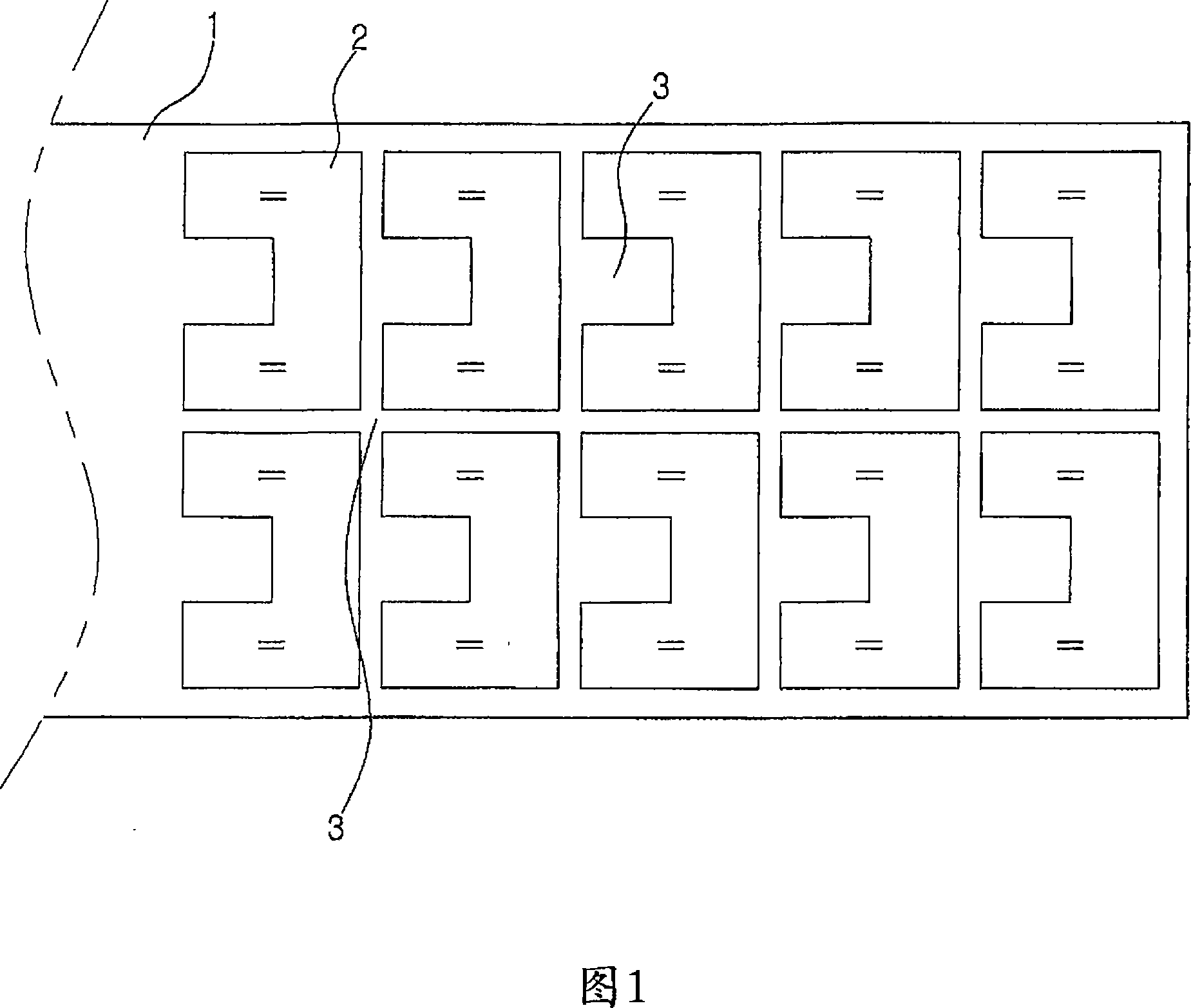
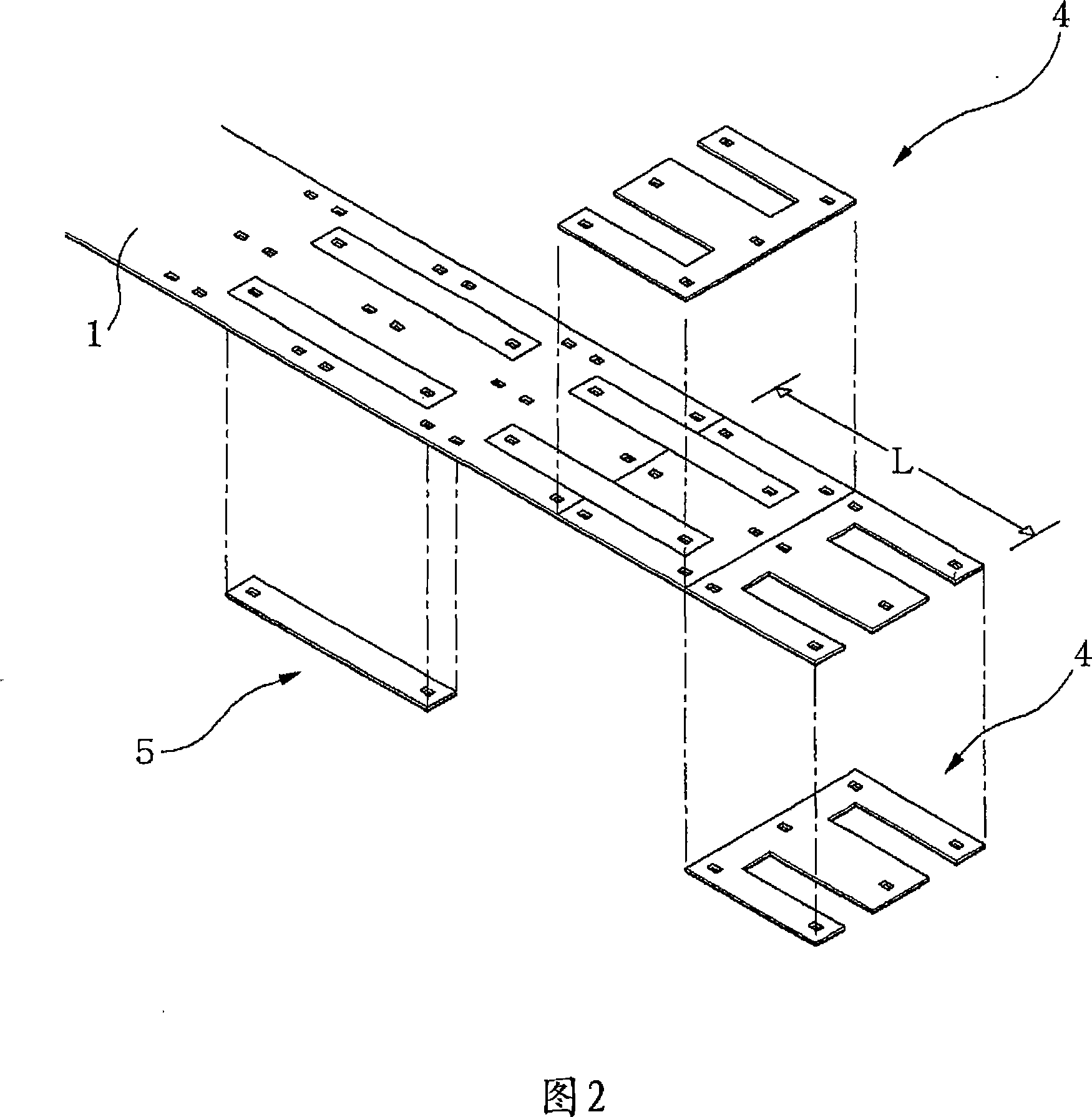
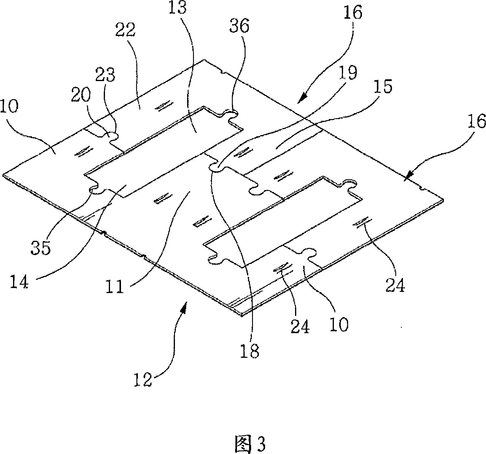
[0042]3 to 6, in the case of forming the iron core according to the present invention, by using a stamping die (not shown) from a silicon steel sheet 17 having a predetermined thickness (usually 0.5mm, or from 0.1mm to 0.35mm) At the same time, the E-shaped iron core 12 and a pair of -shaped iron cores 16 arranged on both sides of the E-shaped iron core 12 are stamped to prevent waste from being produced on the silicon steel sheet 17 .

[0043] The core includes an E-shaped core 12 having: side legs 10 formed in a symmetrical manner on both sides of the E-shaped core; and a bobbin formed between the side legs 10 and coupled to a coil wound thereon. and a stamped groove 14 formed between the side legs 10 and the central leg 11.

[0044] The core also includes a pair of -shaped iron cores 16, each -shaped iron core 16 has: a long leg 2...


PUM


Abstract

An iron core built in a transformer, a rectifier, a stabilizer, a lamp, and others is disclosed. When the iron core is formed, an E-shaped iron core and a pair of c -shaped iron cores, which are arranged on both sides of the E-shaped iron core, are simultaneously stamped from a sheet of silicon steel. A predetermined number of E-shaped iron cores and pairs of c -shaped iron cores are assembled and laminated to form a laminated iron core. The iron core includes the E-shaped iron core having side legs symmetrically formed on both sides thereof and a center leg formed between the side legs and coupled to a bobbin around which a coil is wound, and the pair of C-shaped iron cores each having a long leg formed corresponding to the side leg of the E-shaped iron core and a short leg formed corresponding to the center leg of the E-shaped iron core.

Description

technical field [0001] The present invention relates to an iron core and a die and method for forming and laminating the same, wherein an E-shaped iron core and a pair of -shaped iron cores are continuously formed and laminated when stamping the iron core from a silicon steel sheet by a stamping die, Without loss of steel material (scrap steel). [0002] More particularly, the present invention relates to an iron core installed in transformers, rectifiers, stabilizers, illuminators, and other devices, and molds and methods for forming and laminating the iron core, wherein when the iron core is formed , an E-shaped core and a pair of -shaped cores arranged on both sides of the E-shaped core are simultaneously punched from a silicon steel sheet, and a predetermined number of E-shaped cores and a predetermined number of pairs of -shaped cores are concentrated and laminated to form a stack A piece of iron. Background technique [0003] FIG. 1 is a perspective view illustrat...

Claims


Application Information

Patent Timeline
Patent Type & Authority Applications(China)
IPC IPC(8): B21D28/02
CPCB21D28/02Y10T29/49078Y10T29/5197
Inventor 金明大金明得郑甲均
Owner 金 明大
Why Eureka
Try Eureka