

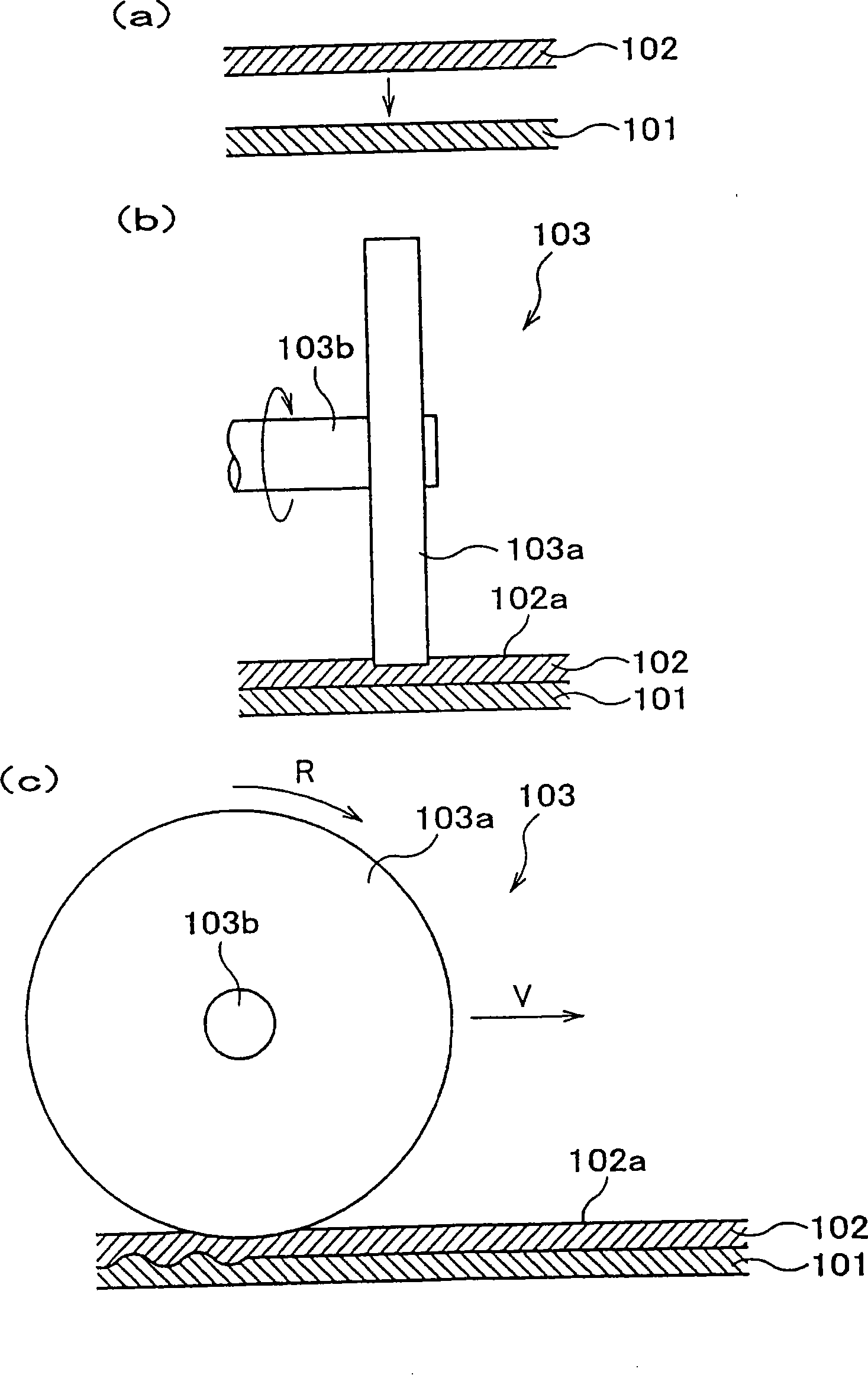
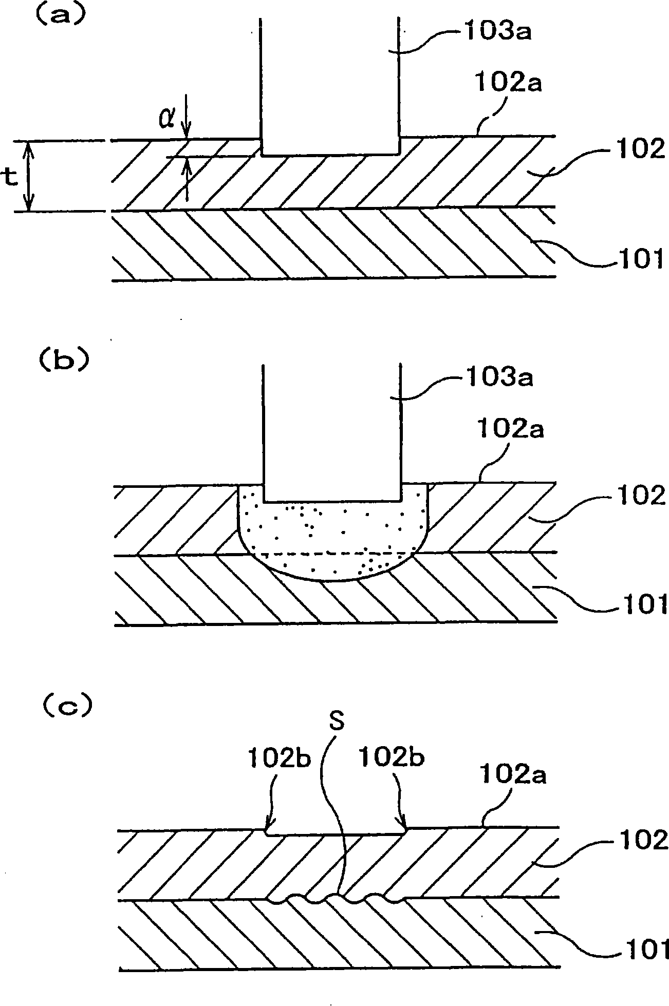
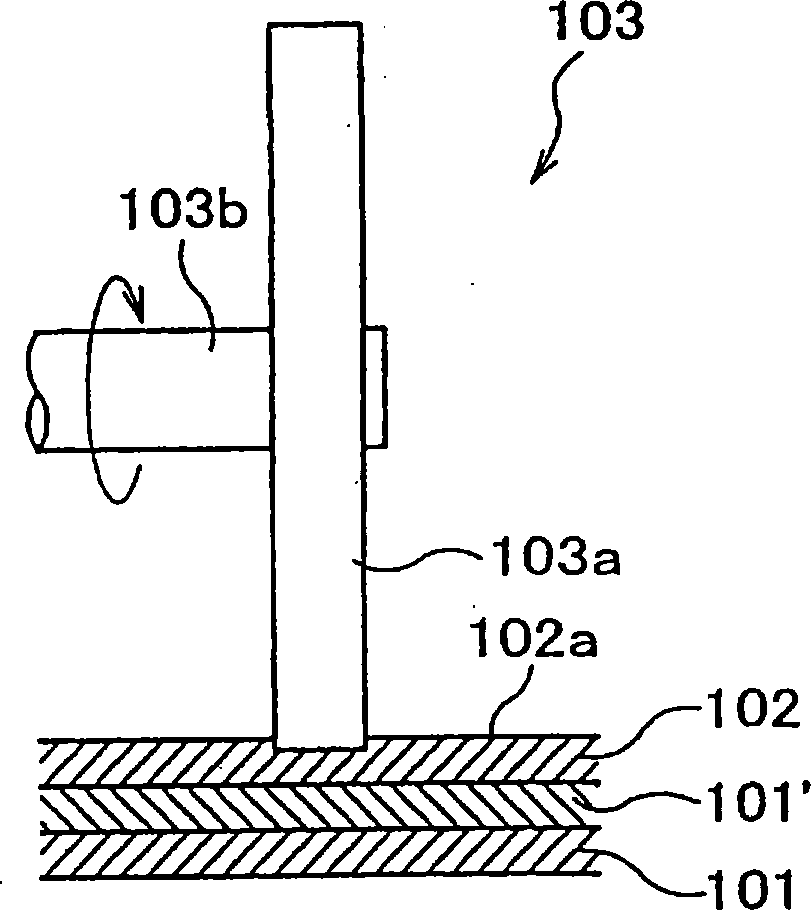
Method of joining metallic members and process for manufacturing radiation member
A bonding method and a technology of metal elements, which are applied in the fields of metal element bonding and heat dissipation element manufacturing, can solve problems such as poor bonding, inability to bond, and fusing of the base end 464a of the fin 464, etc., and achieve high bonding strength and high resistance to deformation The effect of intensity
- Summary
- Abstract
- Description
- Claims
- Application Information
AI Technical Summary
Problems solved by technology
Method used
Image

Examples
Embodiment 1
[0608] Set the width w of the flat surface of the circumferential surface of different joining jigs 1 (mm), groove width w 2 (mm), the ratio of the width of the flat part to the width of the groove w 1 / w 2 Finally, the experimental results of joint quality, appearance and mechanical load are shown in Table 5.
[0609] Table five
[0610]
[0611] ◎: Good / ×: Poor
[0612] ◎: Good / △: Lots of chips / ×: Lots of burrs
[0613] ◎: Light load / ○: Below the specified conditions of the motor
[0614] △: Above the specified conditions of the motor
[0615] ×: Motor stops due to continuous use
[0616] It can be seen from Table 5 that when w 1 / w 2 Too small (comparative example 1-2), because the surface condition of the copper plate will be similar to being cut by the bonding jig, the amount of frictional heat generated by the bonding jig will be larger, the mechanical load will be smaller, and the copper plate will remain on the copper plate after bonding The amo...
Embodiment 2
[0619] After setting the inclination angle of the grooves on the circumferential surface of different bonding fixtures relative to the rotation direction and the number of grooves, the experimental results of the bonding quality, appearance, and mechanical load are shown in Table 6. On the other hand, only in the conditions of Comparative Example 2-2, the width of the joining jig was set to 10 mm.
[0620] Table six
[0621]
[0622] ◎: Good / ×: Poor
[0623] ◎: Good / △: Lots of chips / ×: Lots of burrs
[0624] ◎: Light load / ○: Below the specified conditions of the motor
[0625] △: Above the specified conditions of the motor
[0626] ×: Motor stops due to continuous use
[0627] It can be seen from Table 6 that when the inclination angle of the groove is less than 0.5° (comparative example 2-2), the mechanical load is small, and the plasticized metal accumulated in the groove cannot be sent out sequentially along the width direction of the bonding jig , after ...
Embodiment 3
[0631] After setting the depth of grooves on the circumferential surface of different bonding jigs, the experimental results of bonding quality, appearance, and mechanical load are shown in Table 7.
[0632] Table seven
[0633]
[0634] ◎: Good / ×: Poor
[0635] ◎: Good / △: Lots of chips / ×: Lots of burrs
[0636] ◎: Light load / ○: Below the specified conditions of the motor
[0637] △: Above the specified conditions of the motor
[0638] ×: Motor stops due to continuous use
[0639] It can be seen from Table 7 that when the depth of the groove is less than 0.30mm (comparative example 3-1), the plasticized metal will accumulate inside the groove, which reduces the amount of frictional heat generated by the joining jig, making it impossible to work. sufficient bonding; on the other hand, when the depth of the groove is greater than 1.2mm (comparative example 3-2), because the surface condition of the copper plate will be similar to being cut by the bonding jig, t...
PUM
| Property | Measurement | Unit |
|---|---|---|
| depth | aaaaa | aaaaa |
| thickness | aaaaa | aaaaa |
| thickness | aaaaa | aaaaa |
Abstract
Description
Claims
Application Information