Locking device for non-frame glass door

A technology of locking device and glass door, applied in all-glass wings, building locks, buildings, etc., can solve the problems of short process, short service life, increased safety hazards, etc., and achieve improved service life, long service life, The effect of improving safety

Inactive Publication Date: 2008-04-16
DOOR & WINDOW HARDWARE
View PDF0 Cites 4 Cited by
  • Summary
  • Abstract
  • Description
  • Claims
  • Application Information

AI Technical Summary

Problems solved by technology

[0013] 1. Short service life: After the existing locking device is locked by rotating the lock head 81, the push arm 602 and the push block 714 will be separated, and the operating member 60 can only be maintained in the original position by the first elastic element 604. However, when the handle combined with the operating member 60 is too heavy or the first elastic member 604 is elastically fatigued, it is easy to turn the operating member 60 and then fail to return to its original position automatically. Furthermore, when the first elastic member 604 cannot operate When the member 60 is pulled to the position, the push arm 602 of the operating member 60 will hinder the pushing block 714 of the locking plate 71 from being pushed back to the original position when unlocking, thereby shortening the service life of the existing locking device
[0014] Two, the process is short: when the existing locking device locks the door, it only pushes the linkage arm 72 to move u

Method used


Image

  • Locking device for non-frame glass door
  • Locking device for non-frame glass door
  • Locking device for non-frame glass door

Examples


Embodiment Construction

[0088] In order to further explain the technical means and effects of the present invention to achieve the intended purpose of the invention, the specific implementation, structure, Features and their functions are described in detail below.

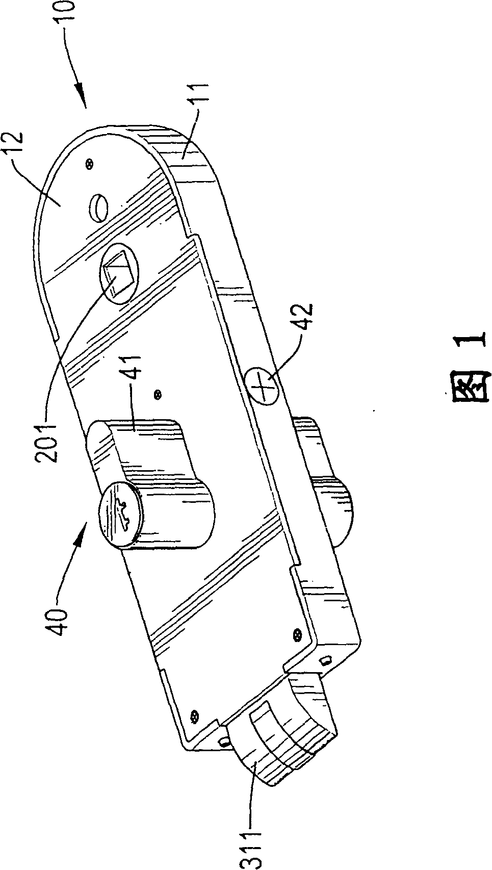
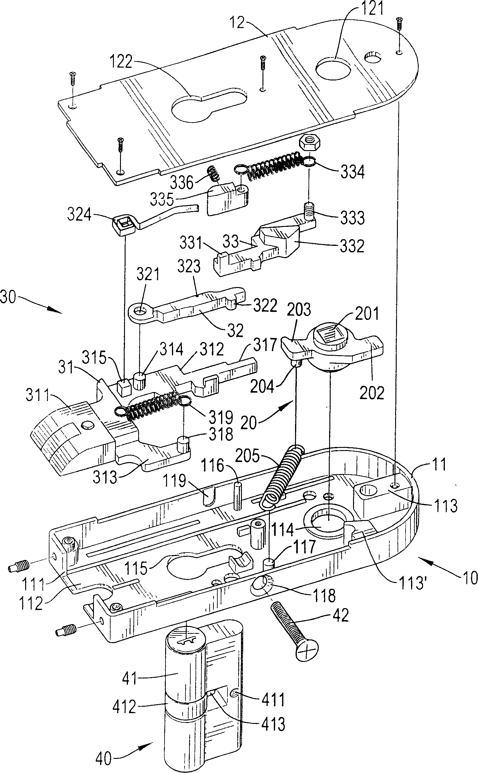
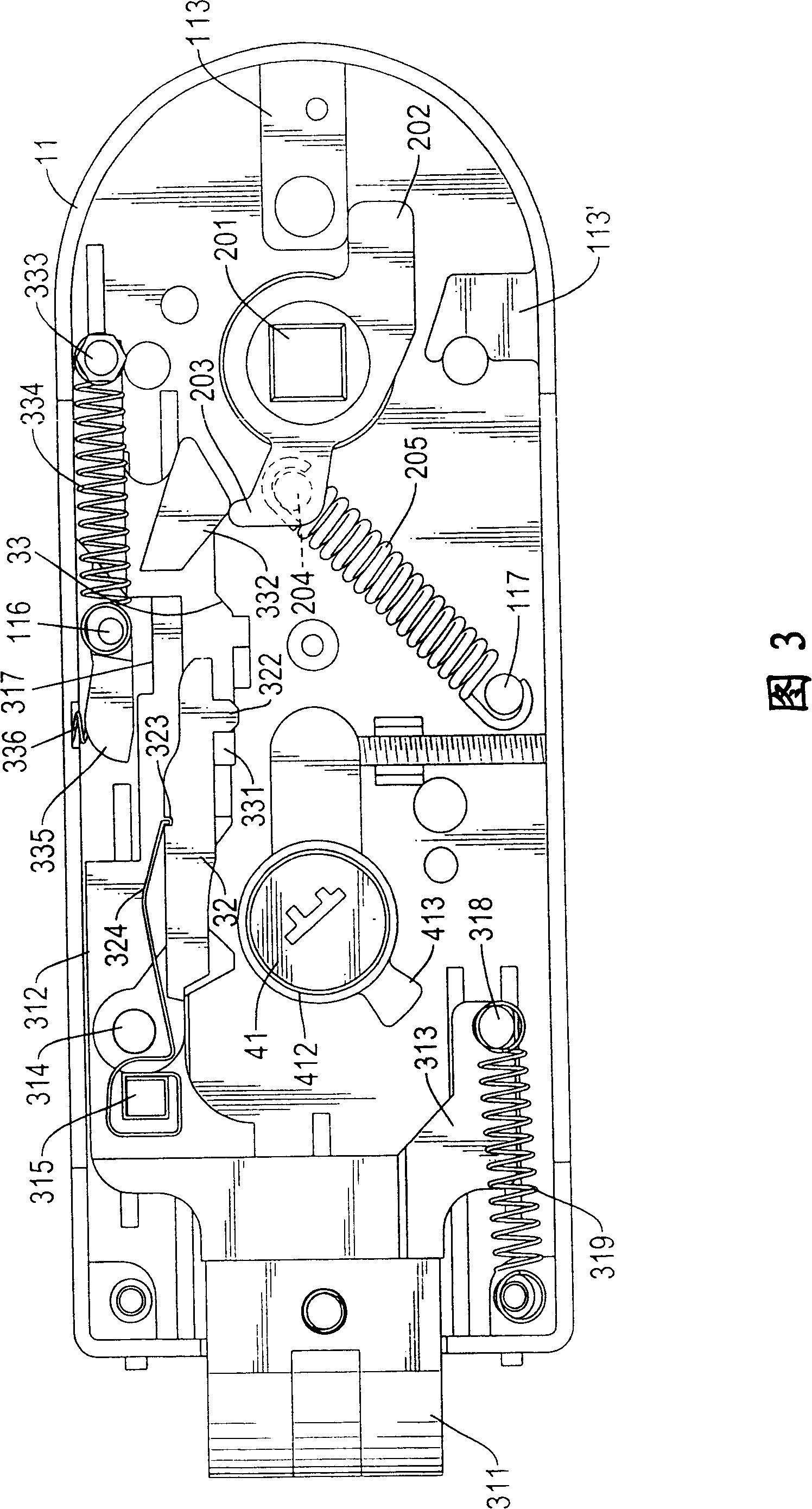
[0089] Please refer to the locking device of the frameless glass door shown in Fig. 1 to Fig. 3 is located on the door, and is provided with a body 10, an operating part 20, an interlocking device 30 and a lock 40, wherein:

[0090]The main body 10 is provided with a box body 11 and a cover plate 12. One end of the box body 11 is provided with an opening 111 and the other end is in a closed shape. A chamber 112 is formed between the opening 111 end and the closed end. An upper limit block 113 is formed on the box body 11 at the end, and an installation hole 114 is perforated on the end edge of the upper limit block 113, and a lower limit block 113' is provided below the installation hole 114, and the box body 11 is in the Between the en...


PUM


Abstract

The invention relates to a securing arrangement of a frameless glass door, comprising a body, an operating piece, a linkage device and a lockset, wherein, the body is provided with a case which is provided with a mounting hole, a lockhole and a lower covering pillar; the operating piece is combined with the mounting hole and provided with a pushing arm which is provided with a covering pole; a first elastic piece is arranged between the covering pole and the lower covering pillar; the linkage device is provided with a clamping plate, a linkage arm and a pulling arm; the clamping plate is provided with a buckling head, an upper combination arm and a lower combination arm; the lower combination arm is protrudent with a lower combination pillar; a second elastic piece is sleeved between the body and the lower combination pillar; a third elastic piece is arranged between the pulling arm and the case, thereby providing the securing arrangement of a frameless glass door which can be operated stably with a long service life and achieve firm locking effect.

Description

technical field [0001] The invention relates to a locking device, in particular to a door lock that can be conveniently, quickly and safely locked, and belongs to the locking device for a frameless glass door belonging to the technical field of door locks. Background technique [0002] In order to prevent strangers or criminals from entering the room, a locking device is generally installed on the door, and the door is fixed by the locking device to achieve the purpose of protection and safety; [0003] Existing locking devices for doors are such as Figure 10 And shown in Figure 11, this door lock device is to be provided with a main body 50, an operating part 60, a linkage device 70 and a lockset 80, wherein the main body 50 is provided with a box body 51, and one end is provided with an opening 511 and the other One end is a closed shape, and a chamber 512 is formed between the opening 511 end and the closed end, and a mounting hole 513 is perforated on the box body 51 ne...

Claims


Application Information

Patent Timeline
IPC IPC(8): E05B65/02E05B15/00E06B3/02
Inventor 张尉弘林清格
Owner DOOR & WINDOW HARDWARE
Why Eureka
Try Eureka