
Image scanner

An image reading device and image information technology, applied in image communication, instrumentation, optics, etc., can solve the problems of high cost and many parts, and achieve the effects of suppressing eccentricity, improving durability, and suppressing load fluctuations

Inactive Publication Date: 2008-04-16
KONICA MINOLTA MEDICAL & GRAPHICS INC
View PDF3 Cites 1 Cited by
  • Summary
  • Abstract
  • Description
  • Claims
  • Application Information

AI Technical Summary

Problems solved by technology

There are many parts used in this structure, and the cost is high. Therefore, it is desired to develop an axial linear motor that can simply and easily accommodate repelling magnets with a simple structure.

Method used


Image

  • Image scanner
  • Image scanner
  • Image scanner

Examples


Embodiment Construction

[0091] Next, first to second embodiments of the present invention will be described with reference to the drawings.

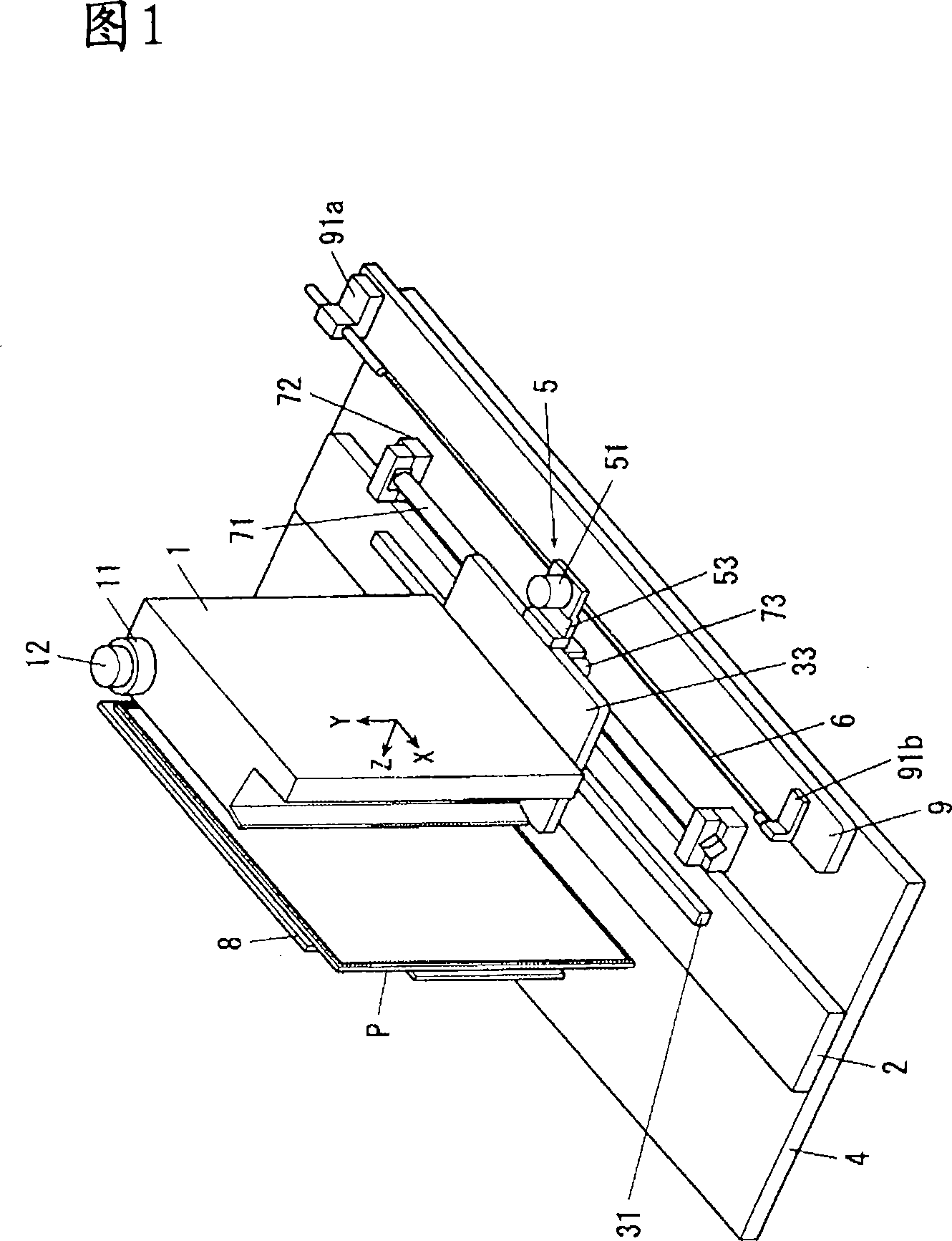
[0092] In the present invention, if the incandescent phosphor sheet is a single body, it has no rigidity and is difficult to handle in the device. Therefore, the case of using a single incandescent phosphor sheet is relatively rare, and in most cases The phosphor sheet is pasted on a support such as a metal plate or a resin plate, or stored in a detachable box called a small box, and glued to the inner surface of the box to support it. In this way, the structure in which the incandescent phosphor sheet is supported on the above-mentioned support or the capsule is formed. In the following description, this structure is referred to as an incandescent phosphor plate. In addition, the support body side of the incandescent phosphor plate is attached to a fixing plate with a rubber magnet or the like, so that the incandescent phosphor plate is supported.

[0093] Th...


PUM


Abstract

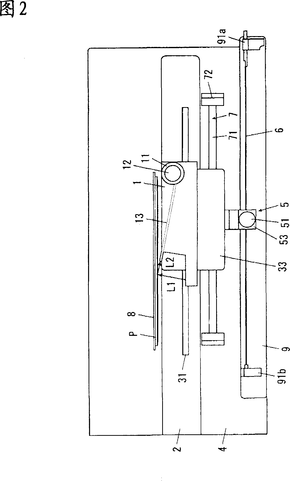
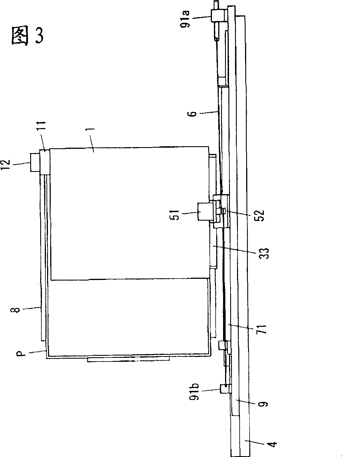
An image scanner which has an improved constant speed characteristic and provides an excellent diagnostic image having no image nonuniformity. The image scanner is provided with an optical unit (1), which irradiates a photostimulable phosphor plate (P) with exciting light (L1) from a light source while performing scanning, collects photostimulated luminescence light emitted from the photolstimulable phosphor plate (P), performs photoelectric conversion and reads image information; a linear motor (7) for moving the optical unit (1); a wire (6) which moves with the optical unit (1); a pulley (52) which rotates by transmission of movement of the optical unit (1) through the wire (6); a rotary encoder (51) for detecting the rotating speed of the pulley (52); and a control means (100) for controlling the linear motor (7) based on the detection results of the rotary encoder (51). The wire (6) is wound around the shaft of the pulley (52) one turn or more by being inclined to be at a prescribed angle from a line (A) orthogonally intersecting with a rotating axis of the pulley (52).

Description

technical field [0001] The present invention relates to an image forming device, and particularly relates to an image reading device which is suitable for use in the medical field and printing field, has good scanning transportability of a luminescent phosphor plate, and uses a shaft-type linear motor. Background technique [0002] Radiographic images such as X-ray images are often used for disease diagnosis and the like. Conventionally, radiographs have been used to obtain such radiographic images. That is, the X-rays that have passed through the object to be irradiated are irradiated on the phosphor layer (fluorescent screen), so that visible light is generated, and the visible light is irradiated on the film using silver salt to develop the image in the same way as in normal photography. , to obtain radiographs. However, the method adopted in recent years is to directly take out the image from the phosphor layer without using a film coated with silver salt. [0003] An...

Claims


Application Information

Patent Timeline
IPC IPC(8): G03B42/02H04N1/04
Inventor 梅村昌弘崎野和弘成田孝之
Owner KONICA MINOLTA MEDICAL & GRAPHICS INC
Learn More