Magnetic induction device

A magnetic induction device and inductance technology, applied in the directions of magnetic recording, electromagnets, inductors, etc., can solve the problems of leakage inductance, can not solve the general mode blocking, etc., to achieve the effect of enhancing the blocking effect and improving the leakage inductance control.

Inactive Publication Date: 2008-04-16
ADVANCED MAGNETIC SOLUTIONS
View PDF7 Cites 4 Cited by
  • Summary
  • Abstract
  • Description
  • Claims
  • Application Information

AI Technical Summary

Problems solved by technology

[0011] Some aspects of techniques and related materials for controlling leakage induction of magnetic components are described in the following publications, but still do not address the general mode blocking problem:
[0015] The following publications describe techniques for reducing the inner coil capacitance of isolation transformers and some aspects of related materials can improve common mode blocking, but they still do not address the problem of controlling leakage inductance:

Method used


Image

  • Magnetic induction device
  • Magnetic induction device
  • Magnetic induction device

Examples


Embodiment Construction

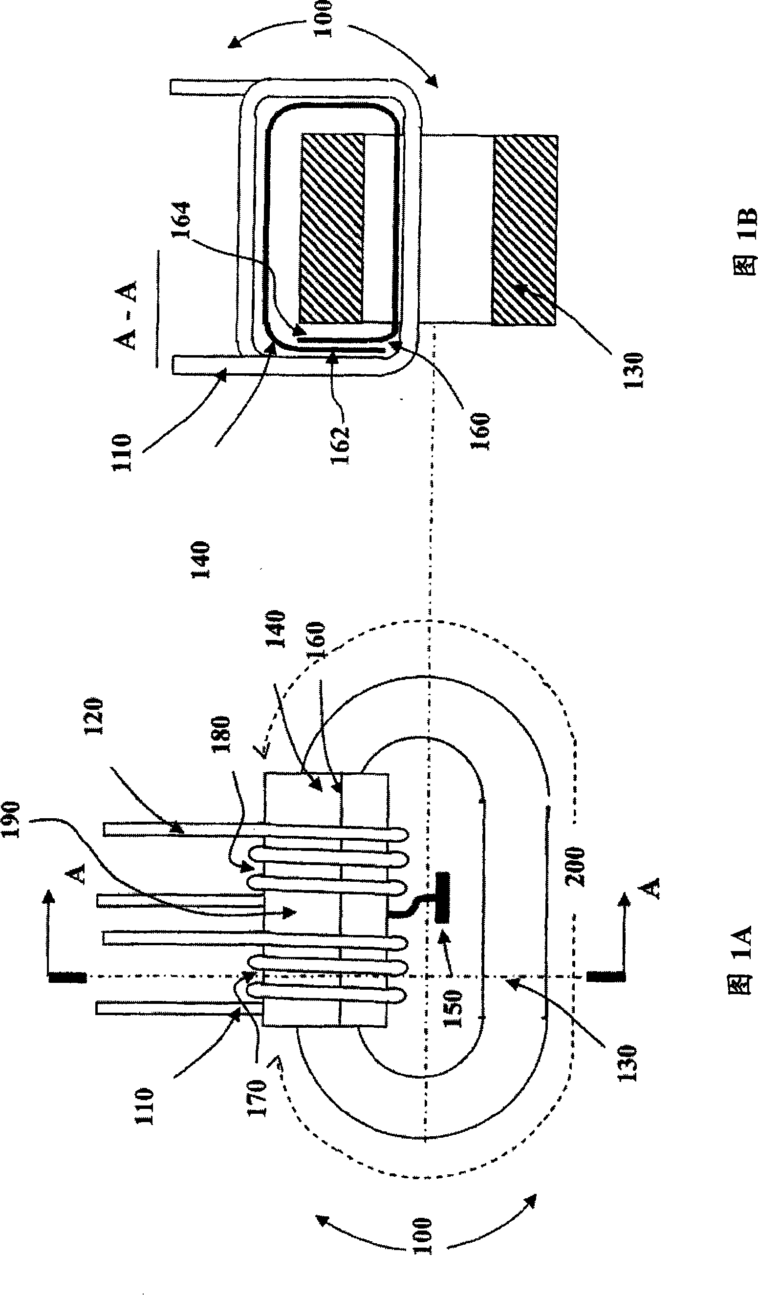
[0064] FIG. 1A schematically illustrates a preferred embodiment of a magnetic induction device (MID) 100 with a transformer employing a grounded conductive cladding (ECC). MID 100 employs a preferred embodiment of the present invention.

[0065] MID100 can be used as various transformers, such as communication. MID 100 preferably includes: at least one primary coil 110; at least one secondary coil 120; a core 130 through which at least one primary coil 110 and at least one secondary coil 120 are magnetically coupled; and an ECC 140. For ease of description, FIG. 1A only shows the primary coil 110 and the secondary coil 120 , but the number of the primary coil and the secondary coil is not limited. The MID 100 may also include multiple primary coils 110 and / or multiple secondary coils 120 .

[0066] Each of the primary coil 110 and the secondary coil 120 may include an insulated conductor formed using a metal deposition technique whereby the conductor is deposited and then an i...


PUM


Abstract

A magnetic induction device (MID) is described. The MID comprises at least one primary electrical winding, at least one secondary electrical winding, and an electrically-conductive cover (ECC) which is electrically connected to a local ground and at least partially surrounds, without forming a closed conductive loop, a core via which the at least one primary electrical winding and the at least one secondary electrical winding are magnetically coupled. Related apparatus and methods are also described.

Description

technical field [0001] The invention relates to a magnetic induction device and a circuit using the magnetic induction device. Background technique [0002] Magnetic induction devices such as transformers and converters (baluns and baluns) are commonly used in various systems, such as communication systems. When a traditional transformer adopts a balanced signal, it generally cannot effectively block the common mode (CM) current in the frequency band above hundreds of MHZ. In high-speed data communication, a sufficiently high CM barrier is especially important to prevent induced and radiated electron currents, thereby reducing data interface noise. [0003] Currently, in composite magnetic devices and designs, traditional signal transformers are still used for communication due to their inadequacy in blocking CM currents. This compound device and design is generally used for 10 / 100 / 1000T Ethernet, and in each pair of lines, it includes a set of line transformers and common...

Claims


Application Information

Patent Timeline
Patent Type & Authority Applications(China)
IPC IPC(8): H01F27/08H01F27/06H01F7/06H01F27/32H01F27/29G11B5/127H05F3/02H02G3/06
CPCH01F2017/0093H01F27/367H01F17/062H01F27/36H01F27/363H01F27/06H01F7/06G11B5/127
Inventor 亚历克斯·阿克塞尔罗德泽夫·什皮罗
Owner ADVANCED MAGNETIC SOLUTIONS
Why Eureka
Try Eureka