Transformer and plate coil molded body

A transformer and plate-shaped technology, which is applied in the field of transformers, can solve the problems of complicated transformer process and inconsistent winding position, and achieve the effects of reducing assembly process, improving productivity, and consistent coupling coefficient

Active Publication Date: 2017-02-15
SOLUM CO LTD
View PDF10 Cites 5 Cited by
  • Summary
  • Abstract
  • Description
  • Claims
  • Application Information

AI Technical Summary

Problems solved by technology

However, since the primary coil and the secondary coil provided in the transformer should be isolated from each other in order to secure a space for the insulation distance required between the coils and satisfy safety standards, the process for manufacturing the transformer is complicated.
[0004] In addition, in the case of winding a coil, the number of turns of the coil and / or the winding position of the coil may not be uniform according to individual workers

Method used


Image

  • Transformer and plate coil molded body
  • Transformer and plate coil molded body
  • Transformer and plate coil molded body

Examples


no. 1 example

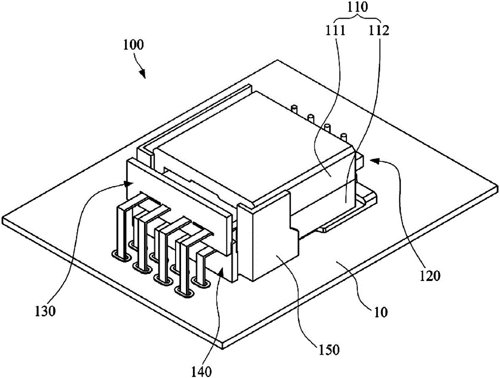
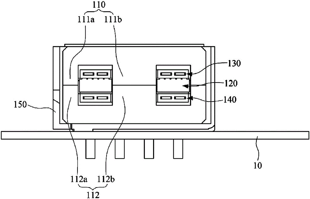
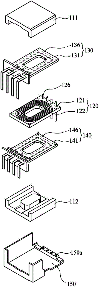
[0057] figure 1 Is a perspective view of the transformer according to the first embodiment of the present disclosure, figure 2 Yes figure 1 Cross-sectional view of a new transformer. image 3 Yes figure 1 Exploded perspective view of the transformer, Figure 4 From image 3 A perspective view of the upper secondary coil module and the lower secondary coil module extracted from the transformer.

[0058] Reference Figure 1 to Figure 4 , The transformer 100 according to the first embodiment of the present disclosure includes a magnetic core 110, a primary coil module 120, an upper secondary coil module 130, and a lower secondary coil module 140.

[0059] The magnetic core 110 is formed with an internal space, and the front and rear sides of the magnetic core 110 are formed in an open shape. Here, for ease of explanation, the front and the rear are defined based on the directions in which the primary coil module 120 and the upper secondary coil module 130 and the lower secondary coil ...

no. 2 example

[0104] Figure 7 Is a perspective view of the transformer according to the second embodiment of the present disclosure, Figure 8 Yes Figure 7 Side section view of the transformer, Picture 9 Yes Figure 7 Exploded perspective view of the transformer, Picture 10 From Picture 9 A perspective view of the upper secondary coil module and the lower secondary coil module extracted from the transformer.

[0105] Reference Figure 7 to Figure 10 , The transformer 200 according to the second embodiment of the present disclosure includes a magnetic core 210, a primary coil module 220, an upper secondary coil module 230, and a lower secondary coil module 240. Here, the magnetic core 210 and the primary coil module 220 according to this embodiment may be configured in the same manner as the magnetic core 110 and the primary coil module 120 according to the first embodiment.

[0106] The upper plate-shaped coil 236 has inner and outer ends exposed from the upper insulating molded body 231 and...

no. 3 example

[0117] Picture 12 Is a perspective view of a transformer according to a third embodiment of the present disclosure, Figure 13 Yes Picture 12 Side section view of the transformer, Picture 14 Yes Picture 12 Exploded perspective view of the transformer, Figure 15 From Picture 14 A perspective view of the upper secondary coil module and the lower secondary coil module extracted from the transformer.

[0118] Reference Figure 12 to Figure 15 , The transformer 300 according to the third embodiment of the present disclosure includes a magnetic core 310, a primary coil module 320, an upper secondary coil module 330, and a lower secondary coil module 340. Here, the primary coil module 320 according to this embodiment may be configured in the same manner as the primary coil module 120 according to the first embodiment.

[0119] The upper core 311 protrudes from the left and right edges of the lower surface of the upper core 311 in accordance with a pair of first legs 311a to contact t...


PUM


Abstract

The invention provides a transformer and a plate coil molded body. The transformer includes a magnetic core, a primary coil module including a coil support arranged in the magnetic core and a primary coil formed on the coil support, an upper secondary coil module including an upper insulation molded body arranged on an upper portion of the primary coil module and an upper plate coil buried in the upper insulation molded body and arranged to face the primary coil, and a lower secondary coil module including a lower insulation molded body arranged on a lower portion of the primary coil module and a lower plate coil buried in the lower insulation molded body and arranged to face the primary coil.

Description

[0001] This application claims priority with Korean patent applications No. 10-2015-0109156 and 10-2015-0125713 filed at the Korean Intellectual Property Office on July 31, 2015 and September 4, 2015, respectively. The Korean patent application The public content of is included here by reference. Technical field [0002] The present invention relates to a transformer provided in a power supply device or the like. Background technique [0003] The power unit is provided in the power supply device. The size of the transformer provided in the power unit is approximately 1 / 3 of the total size of the power unit. Transformers have a small number of components (including cores, coil formers and coils). However, since the primary coil and the secondary coil provided in the transformer should be isolated from each other in order to ensure a space for the required insulation distance between the coils and meet safety standards, the process for manufacturing the transformer is complicated....

Claims


Application Information

Patent Timeline
Patent Type & Authority Applications(China)
IPC IPC(8): H01F27/28H01F27/30H01F27/32H01F27/24
CPCH01F27/24H01F27/2866H01F27/306H01F27/324H01F27/2804H01F27/2823H01F27/2847H01F27/325H01F2027/2819
Inventor 朴根泳张凤虎严在根卢永昇崔兴均金熙昱
Owner SOLUM CO LTD
Why Eureka
Try Eureka