Transformer

A technology for transformers and secondary windings, which is applied in the field of transformers and can solve problems such as the volume increase of transformers 1

Inactive Publication Date: 2006-11-22
MATSUSHITA ELECTRIC WORKS LTD
View PDF1 Cites 5 Cited by
  • Summary
  • Abstract
  • Description
  • Claims
  • Application Information

AI Technical Summary

Problems solved by technology

[0009] However, if a shield is provided in the transformer, terminals used for the shield must be provided in addition to the shield, which increases the size of the transformer 1

Method used


Image

  • Transformer
  • Transformer
  • Transformer

Examples


Embodiment Construction

[0027] Embodiments of the present invention will be described below with reference to the drawings.

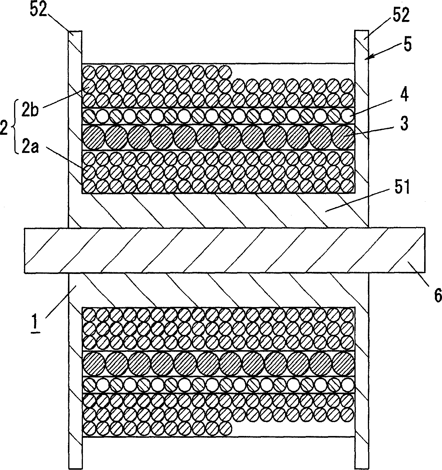
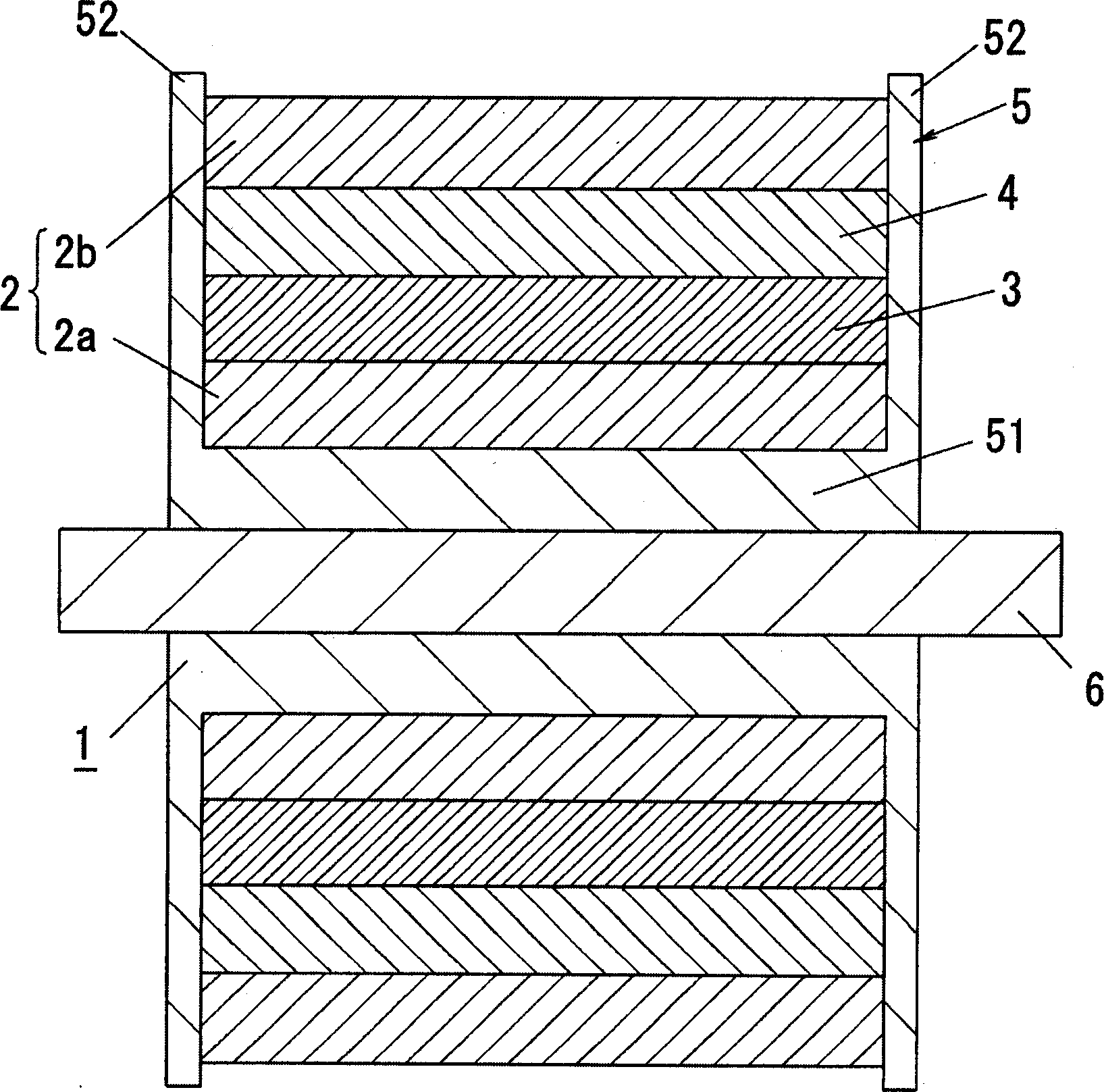
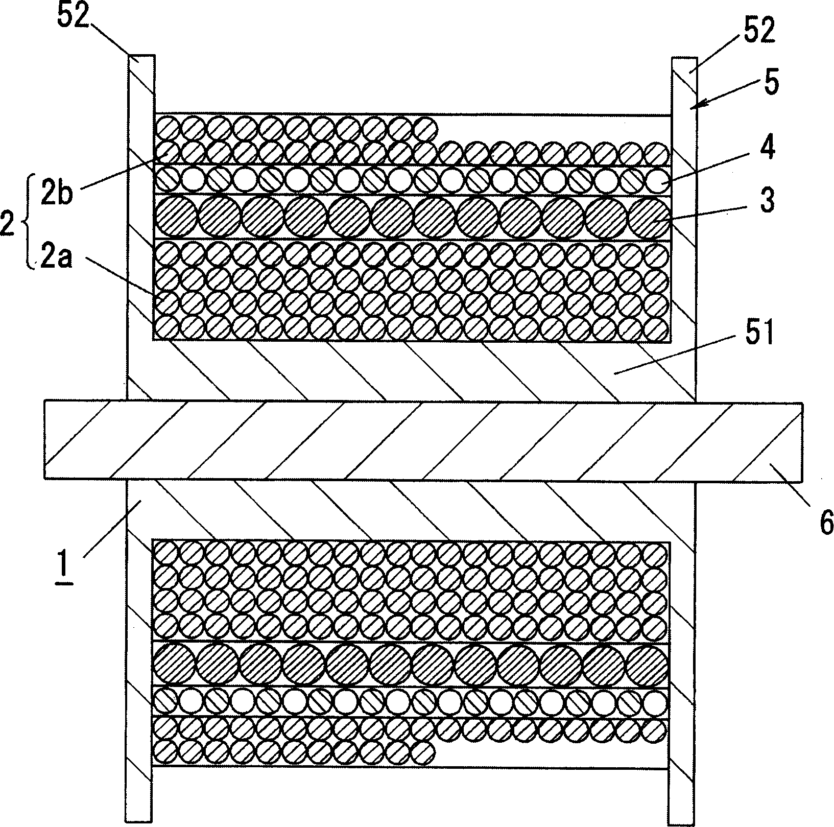
[0028] Transformer 1 of this embodiment, such as figure 2 As shown, it includes a cylindrical shaft portion 51 made of insulating material with a uniform outer diameter and a flange portion 52 protruding from both ends of the shaft portion 51 along the radial direction of the shaft portion 51; The magnetic body constitutes and penetrates the magnetic core 6 of the shaft portion of the bobbin 5; between the flange portions 52 of the bobbin 5, it is divided into four overlapping winding layers in the radial direction of the shaft portion 51 relative to the shaft portion 51, The primary winding 2, the secondary winding 3, and the feedback winding 4 wound on the shaft portion 51. The primary winding 2 includes the winding layer 2a located on the innermost side (hereinafter referred to as “the first layer”) and counting from the inside. The winding layer 2b of the fourth layer (h...


PUM


Abstract

A transformer is provided in which leakage inductance and electro-magnetic noise can be reduced without making the transformer larger. This transformer includes a primary winding, a secondary winding and a feedback winding, in which: each winding is wound onto a bobbin so that four winding layers are separately piled in the radius directions of the bobbin's shaft portion; the primary winding is formed by the innermost winding layer and the forth winding layer from the inside; the secondary winding is formed by the second winding layer from the inside; the feedback winding is formed by the third winding layer from the inside; and the feedback winding is wound substantially with no clearance from a position adjacent to one flange portion of the bobbin to a position adjacent to the other flange portion of the bobbin.

Description

technical field [0001] The present invention relates to a transformer for switch mode power supply, in particular to a transformer for RCC (Ringing Choke Converter) mode switch mode power supply. technical background [0002] In the prior art, there is a kind of Figure 6 The shown transformer 1 is called a self-excited flyback switching power supply of the RCC system. [0003] below, yes Figure 6 The switching power supply is described in detail. The switching power supply includes a transformer 1, and the transformer includes a rectifying circuit 7 for rectifying the output of the AC power supply, and a primary circuit connected between the output terminals of the rectifying circuit through a series circuit of a switching element Q1 composed of FETs and a resistor R4. A winding 2, a secondary winding 3 connected between the output terminals via a diode D3, one end of which is grounded and the other end is connected to the gate of the switchi...

Claims


Application Information

Patent Timeline
Patent Type & Authority Applications(China)
IPC IPC(8): H01F27/36H01F27/28
CPCH01F27/323H01F27/346H01F27/38H01F38/42H02M3/338H01F27/36H01F27/363
Inventor 北村浩康山下干弘
Owner MATSUSHITA ELECTRIC WORKS LTD
Why Eureka
Try Eureka