Transformer for multi-output power supplies

a transformer and multi-output technology, applied in the direction of transformer/react mounting/support/suspension, transformer/inductance magnetic core, core/yoke, etc., can solve the problem of difficult to provide a suitable transformer for multi-output power supplies using a common magnetic core, and can pose significant challenges to the designer, etc. problem, to achieve the effect of simplifying manufacturing and construction, reducing the number of windings, and simple manner

Active Publication Date: 2009-09-03
TEXAS INSTR INC
View PDF12 Cites 6 Cited by
  • Summary
  • Abstract
  • Description
  • Claims
  • Application Information

AI Technical Summary

Benefits of technology

[0005]According to the invention there is provided a transformer for multi-output power supplies comprising a magnetic core and a plurality of windings, at least some of which give effect to fractional windings, arranged about the magnetic core, characterised in that the transformer further comprises a dual transformer structure having a main transformer and an auxiliary transformer. By having such a transformer it is possible to use readily available and relatively inexpensive planar-type

Problems solved by technology

However, there are numerous difficulties associated with this approach.
First of all, by placing the plurality of windings about a common magnetic core, this can cause difficulties particularly when working with low voltages, as frequently fractional turns are required in order to achieve the desired conversion ratio.
Fractional turns may be implemented very simply conceptually using a multi-leg core, typically an X-core, but the practical implementation can pose significant challenges to

Method used


Image

  • Transformer for multi-output power supplies
  • Transformer for multi-output power supplies
  • Transformer for multi-output power supplies

Examples


Embodiment Construction

[0025]The invention will now be more clearly understood from the following description of some embodiments thereof, given by way of example only with reference to the accompanying drawings, in which:—

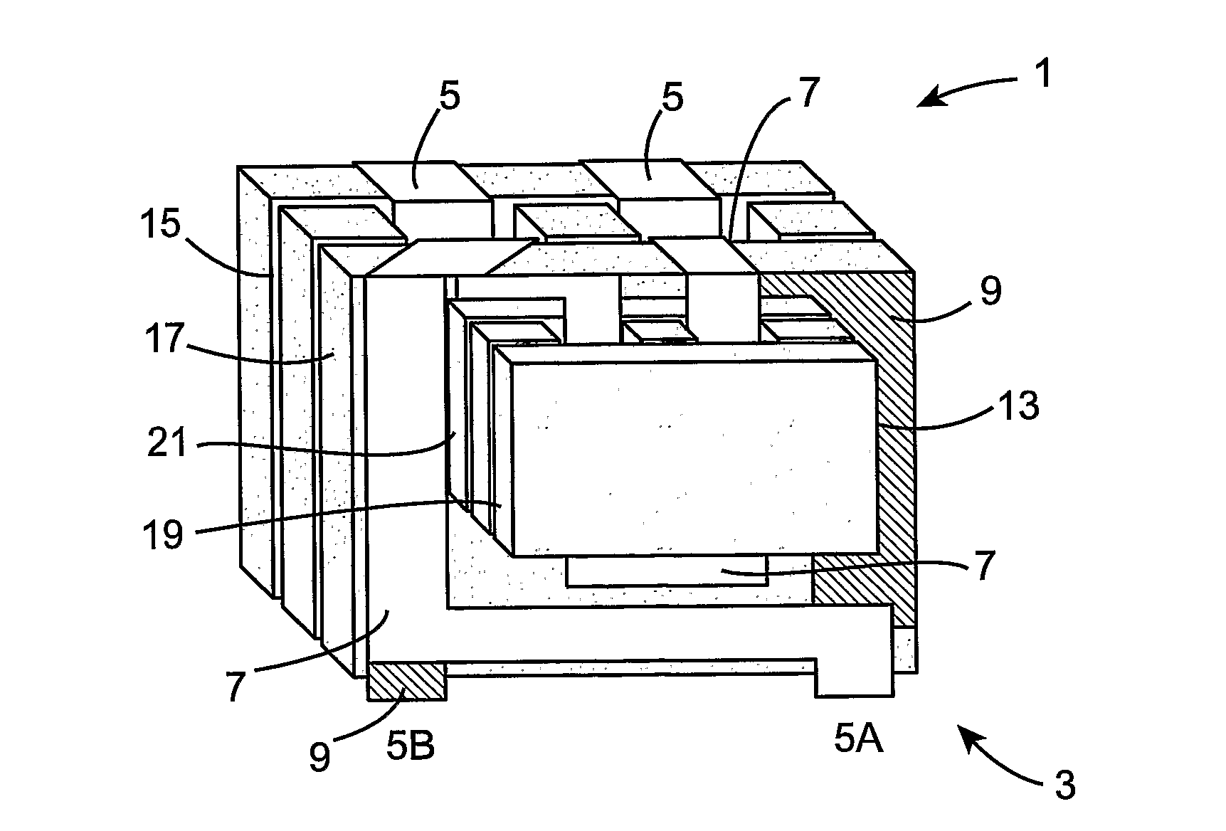
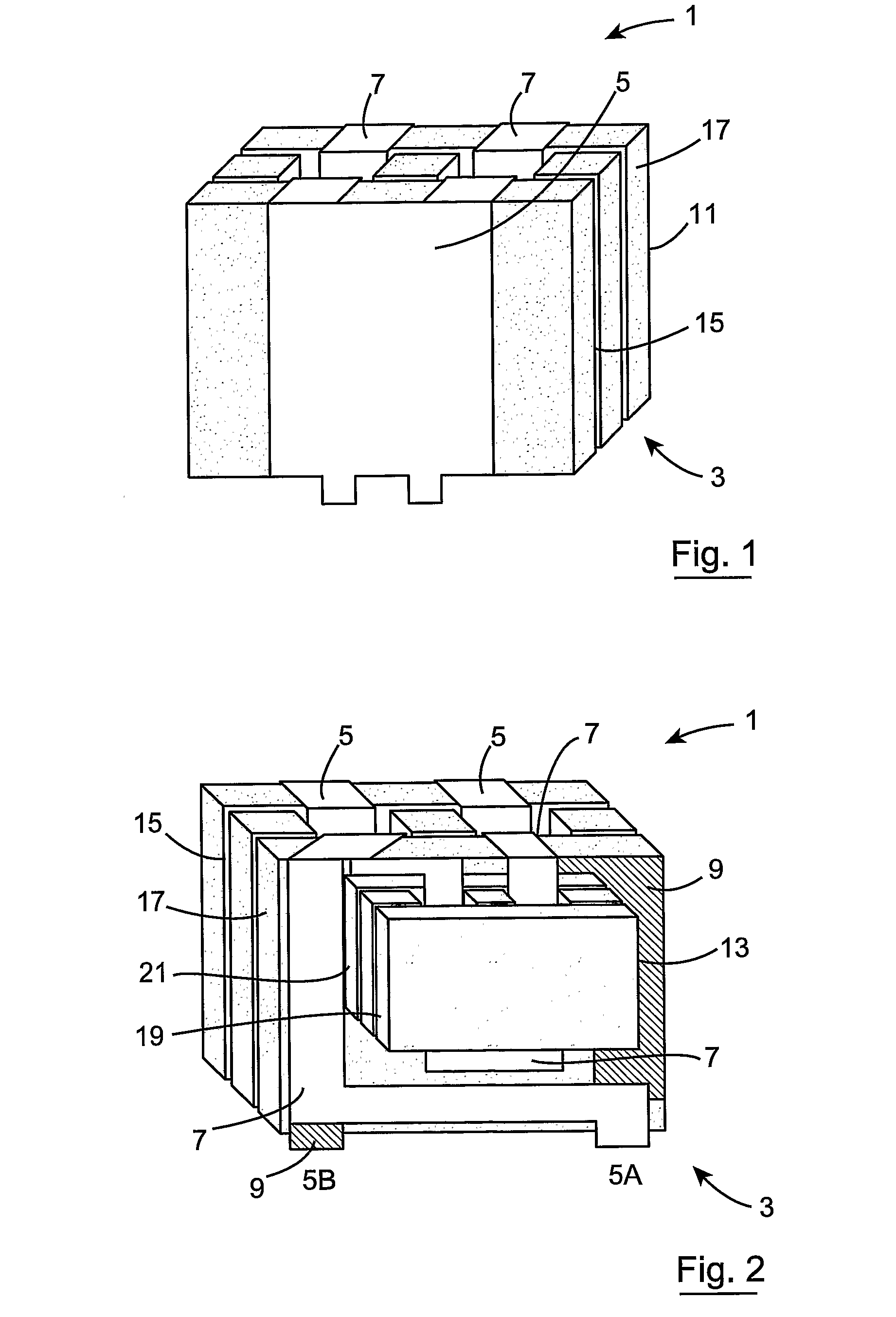
[0026]FIG. 1 is a front perspective view of a transformer for multi-output power supplies according to the invention;

[0027]FIG. 2 is rear perspective view of the transformer shown in FIG. 1;

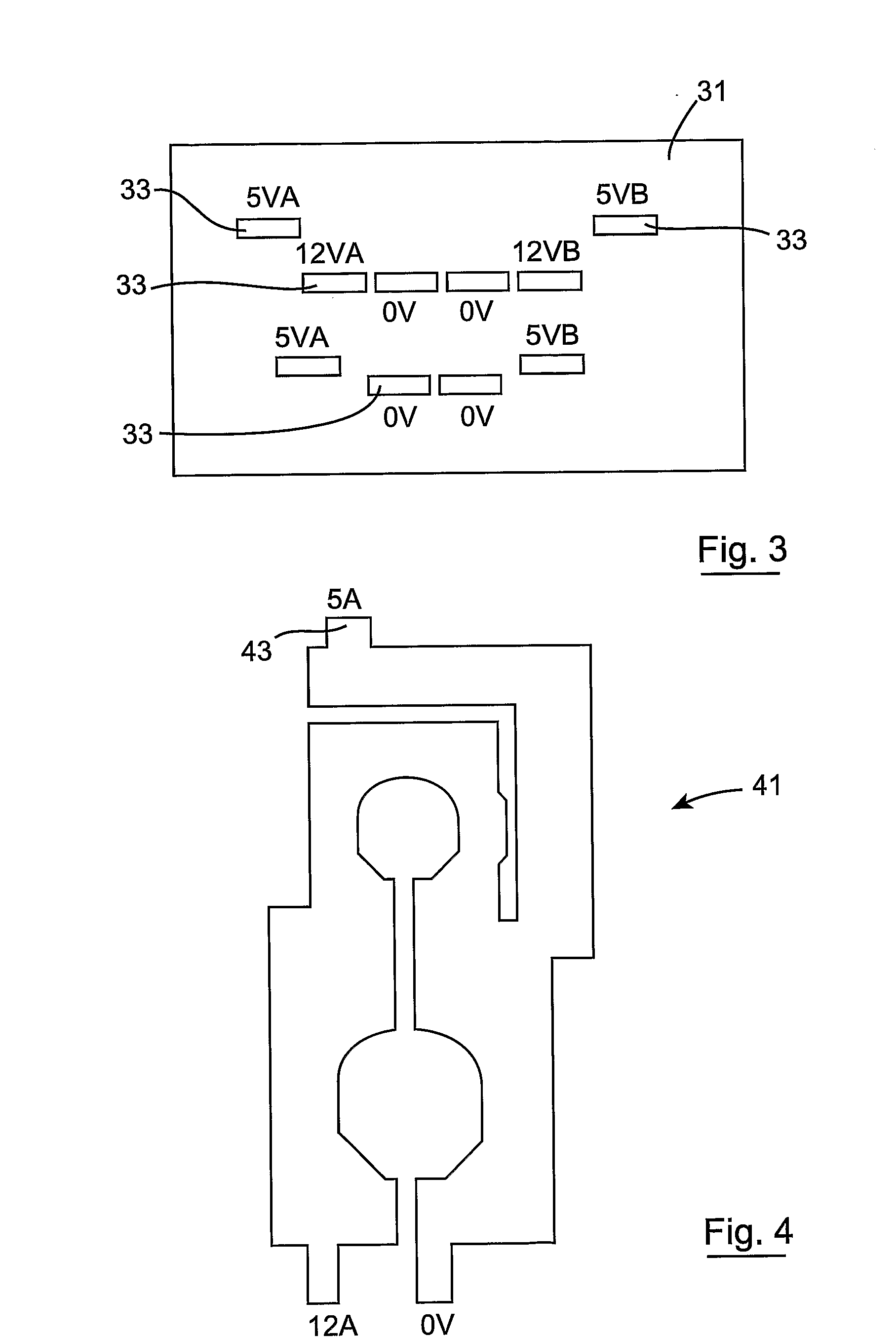
[0028]FIG. 3 is a diagrammatic representation of the outline footprint of the transformer of FIGS. 1 and 2;

[0029]FIG. 4 is a plan view of a 12V winding;

[0030]FIG. 5 is a front perspective view of an alternative construction of transformer according to the invention;

[0031]FIG. 6 is a plan view of an alternative construction of winding used in the transformer according to the present invention; and

[0032]FIG. 7 is a side cross-sectional view of a transformer according to the present invention.

[0033]Referring to the drawings and initially to FIGS. 1 and 2 thereof, there is shown a transformer, indicated ...


PUM


Abstract

This invention relates to a transformer (1) for multi-output power supplies such as those commonly found in electronic equipment. The transformer comprises a magnetic core (3) and a plurality of windings (5, 7, 9) at least some of which are fractional windings, arranged about the magnetic core. The transformer comprises a dual transformer structure with a pair of transformers, a main transformer (11) and an auxiliary transformer (13). In a preferred embodiment, the main transformer and the auxiliary transformer are connected together. In this way, readily available magnetic components may be used in the construction of the transformer and the simple construction allows for a large cross-sectional area of transformer to be deployed so that reduced turn counts of windings may be used.

Description

[0001]This invention relates to a transformer for multi-output power supplies comprising a magnetic core and a plurality of windings, at least some of which being fractional windings, arranged about the magnetic core.[0002]It is not uncommon to have transformers that are required to provide a number of output power supplies for use in the operation of electronic equipment. One such example is that found in the standard desk-top power supplies with the “ATX set” of 12 V, 5V, 3V3 and −12V supplies being provided. Typically, an incoming AC mains line voltage is converted into a DC voltage suitable for manipulation in the transformer, and the transformer thereafter transforms the suitable DC voltage into each of the required DC voltage levels. By and large, the required DC voltage levels are obtained by controlling the number of secondary winding turns on the transformer. Normally, it is considered advantageous to provide all of the windings of a transformer on a common magnetic core. T...

Claims


Application Information

Patent Timeline
IPC IPC(8): H01F27/06H01F27/28
CPCH01F3/10H01F27/2847H02M3/33561H01F30/04H01F30/10H01F27/38
Inventor YOUNG, GEORGE
Owner TEXAS INSTR INC
Why Eureka
Try Eureka