Stop position control method and apparatus of rotary stencil printing press

A technology of stop position and printing method, which is applied to rotary printing machines, general parts of printing machinery, printing machines, etc., can solve the problems of shortened life of motors and motor bearings, deterioration of grease, and increased power consumption, etc., to achieve Conducive to diversification, increase the degree of freedom, improve the effect of life

Inactive Publication Date: 2008-04-23
KOMORI CORP
View PDF0 Cites 4 Cited by
  • Summary
  • Abstract
  • Description
  • Claims
  • Application Information

AI Technical Summary

Problems solved by technology

[0003] However, in conventional rotary screen printing machines, the type of ink and the size of the hole that can be used are limited. As a result, not only the printed matter that can be printed is limited, Moreover, since the rotary screen printing machine must be rotated when the printing is stopped, the current also flows through the motor and the motor driver during the printing stop. In addition to increasing the power consumption, the motor also generates heat, which causes the motor to and the grease in the bearing part of the motor deteriorates, shortening the life of the motor and the bearing part of the motor, etc.

Method used


Image

  • Stop position control method and apparatus of rotary stencil printing press
  • Stop position control method and apparatus of rotary stencil printing press
  • Stop position control method and apparatus of rotary stencil printing press

Examples


no. 1 example

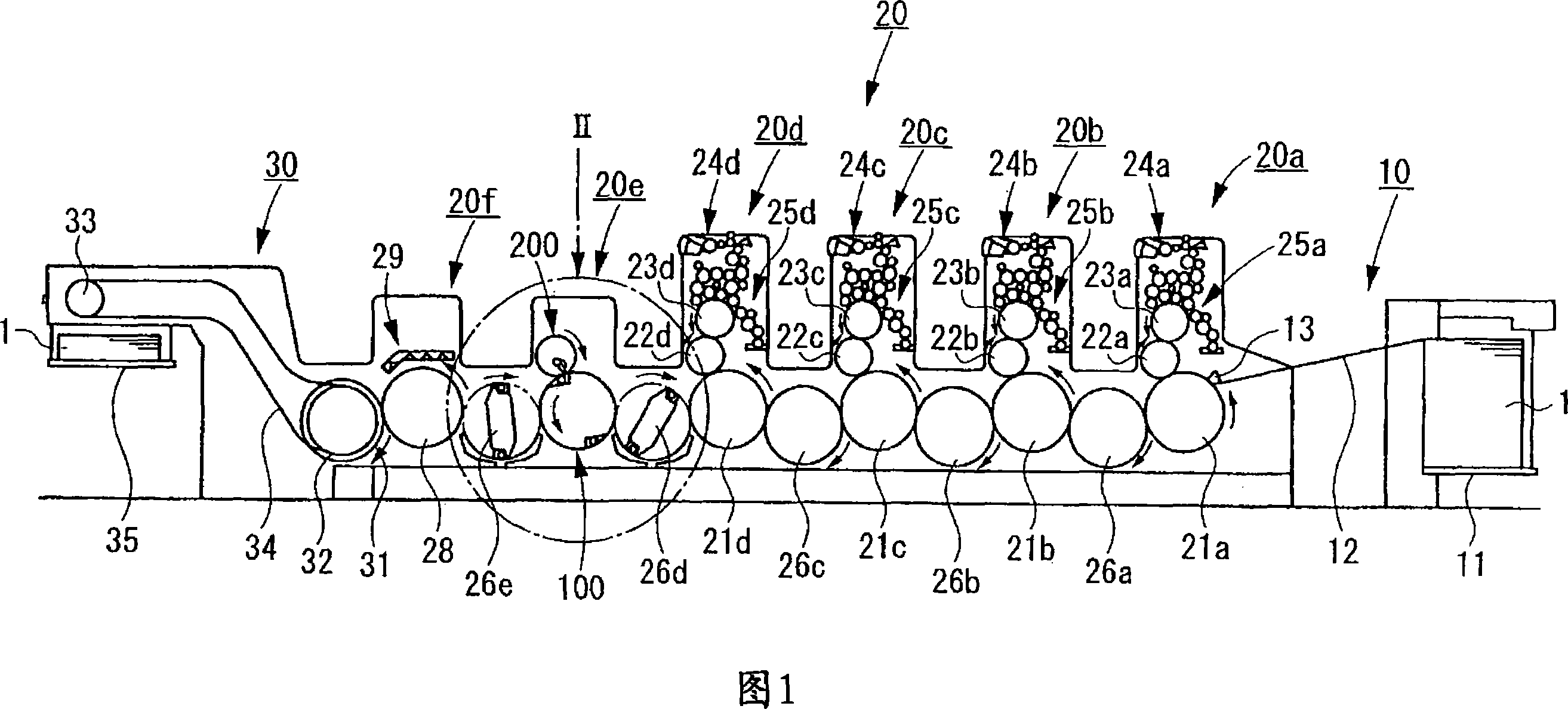
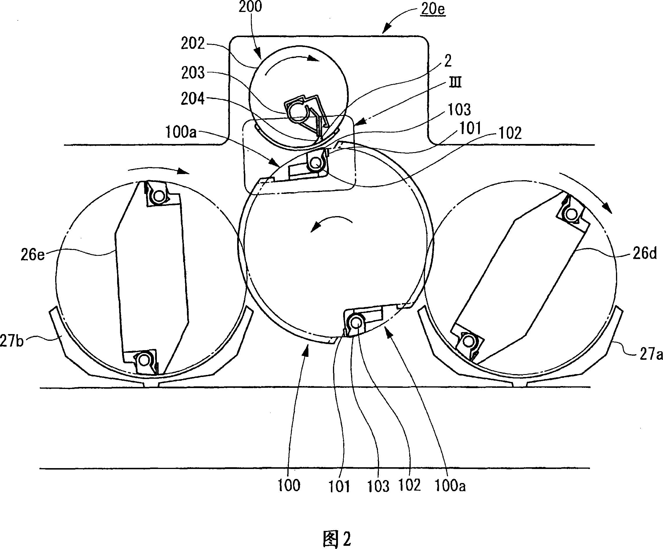
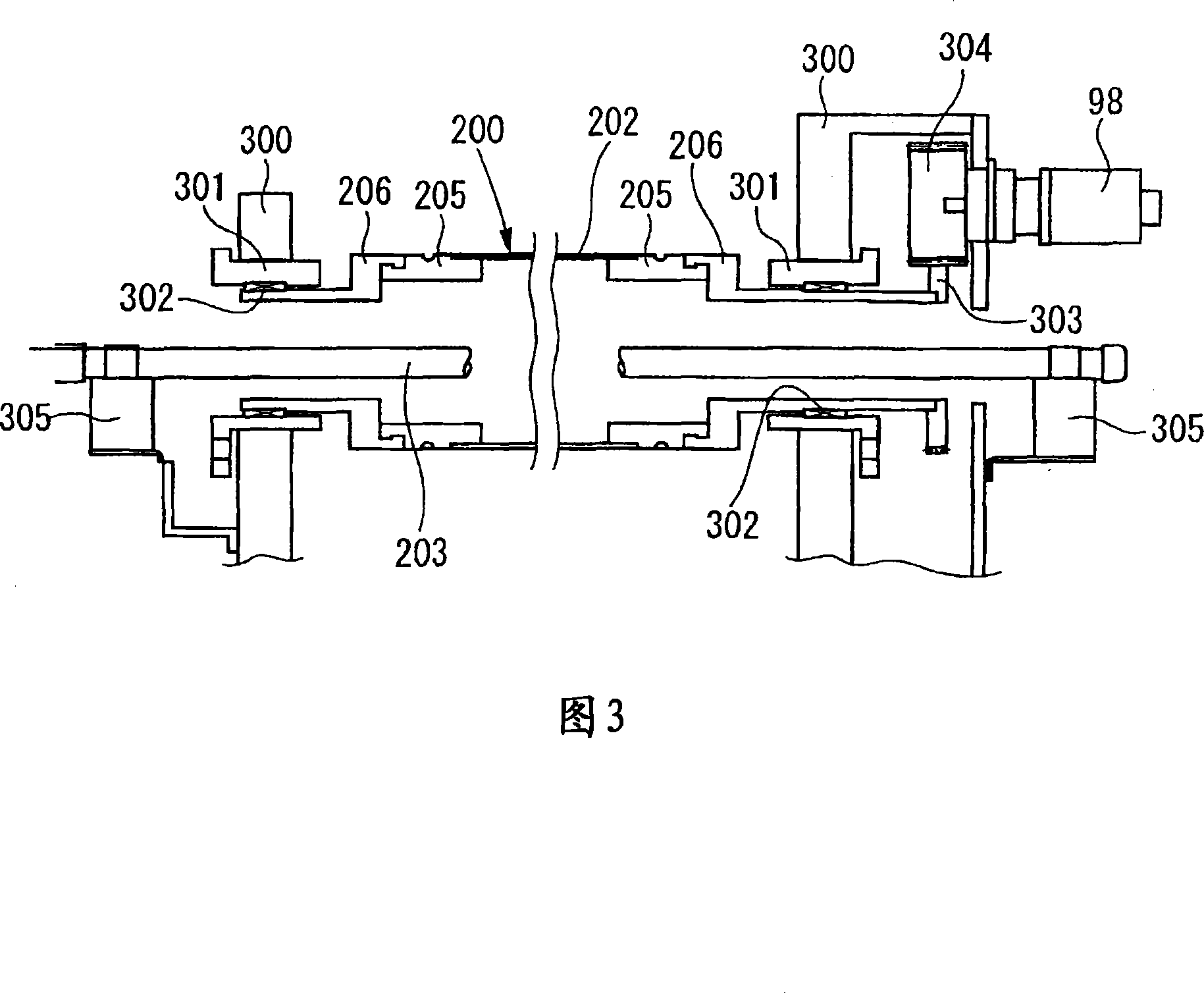
[0072] Fig. 1 is a schematic diagram showing the overall structure of an offset sheet-fed printing machine according to a first embodiment of the present invention; Fig. 2 is an enlarged view of part II in Fig. 1; Fig. 3 is a cross-sectional view of a rotary screen device; A cross-sectional view of the plate vise device of the plate cylinder, Figure 5 is an explanatory diagram of its function, Figure 6 is a block diagram of a drive control device for an offset sheet-fed printing machine, and Figure 7 is a block diagram of a drive control device for a rotary screen cylinder, Fig. 8(a) to 8(d) are the operation flowcharts of the drive control device of the offset sheet-fed printing press, and Fig. 9(a) and Fig. 9(b) are the actions of the drive control device of the offset sheet-fed printing press Flowchart, Fig. 10(a) ~ Fig. 10(c) are the operation flowchart of the drive control device of the offset sheet-fed printing machine, Fig. 11 is the operation flow chart of the drive con...

no. 2 example

[0169] Fig. 15 is a block diagram showing a drive control device for an offset sheet-fed printing machine according to a second embodiment of the present invention, Fig. 16 is a block diagram of a drive control device for a rotary screen cylinder, and Fig. 17(a) to Fig. 17(d) are Figure 18(a)-Figure 18(b) is an action flow chart of the drive control device for the offset sheet-fed printing press, Figure 19(a)-Figure 19 (c) is an action flow chart of the drive control device of the offset sheet-fed printing press, and Fig. 20 is an action flow chart of the drive control device of the offset sheet-fed printing press, and Fig. 21 (a) and Fig. 21 (b) are rotation The action flowchart of the drive control device of the screen cylinder, Figure 22 (a) and Figure 22 (b) are the action flow charts of the drive control device of the rotary screen cylinder, Figure 23 is the action of the drive control device of the rotary screen cylinder flow chart.

[0170] This embodiment is such an exa...


PUM


Abstract

This invention relates to a stop position control method and apparatus of a rotary stencil printing press. In a rotary screen device (200) in which ink is transferred through holes of a screen (202), with a rotary screen cylinder provided with the screen (202) being rotated, to carry out printing, the rotary screen cylinder is stopped, in accordance with a stop signal, at a position at which a pattern-free portion (a hole-free portion) (A) of the screen (202) comes to a lowermost position. Since the rotation of a stencil printing press is stopped in a rotation phase in which the pattern-free portion of the screen comes to the lowermost position, ink is prevented from dripping through the holes of the screen (202).

Description

technical field [0001] The invention relates to a stop position control method and a control device of a rotary stencil printing machine. Background technique [0002] In the past, in the rotary screen printing machine, when the printing was stopped, in order to prevent the ink from dripping from the holes of the screen printing plate, in addition to keeping the rotary screen printing machine rotating when the printing was stopped, consideration should also be given to The viscosity of the ink and the size of the hole, the combination of the ink that will not drip and the size of the hole is used for printing. [0003] However, in the conventional rotary screen printing machine, the type of ink that can be used and the size of the hole are limited. As a result, not only the printed matter that can be printed is limited, but also because the rotary screen printing machine must be stopped when printing stops. Rotation, so in the process of stopping the printing, the current a...

Claims


Application Information

Patent Timeline
Patent Type & Authority Applications(China)
IPC IPC(8): B41F33/08B41F21/00B41F15/08
CPCB41F33/08B41F15/0809B41P2233/00
Inventor 沼内裕光小室惠佐夫日下明广
Owner KOMORI CORP
Why Eureka
Try Eureka