Circuit board transporting device
A technology for transporting devices and circuit boards, applied in the directions of transportation and packaging, multi-axis trolleys, trolley accessories, etc., can solve the problems of easy damage to circuit boards, easy collision and friction of circuit boards, etc., to avoid collision or friction damage, gravity increased effect
Inactive Publication Date: 2018-06-01
宁波隆锐机械制造有限公司
View PDF0 Cites 3 Cited by
- Summary
- Abstract
- Description
- Claims
- Application Information
AI Technical Summary
Problems solved by technology
Secondly, during transportation, the circuit boards are prone to collision and friction, and the circuit boards are easily damaged
Method used
View moreImage
Smart ImageViewing Examples
Examples
Embodiment Construction
[0019] Below in conjunction with accompanying drawing and specific embodiment the present invention will be described in further detail:
Login to View More PUM
 Abstract
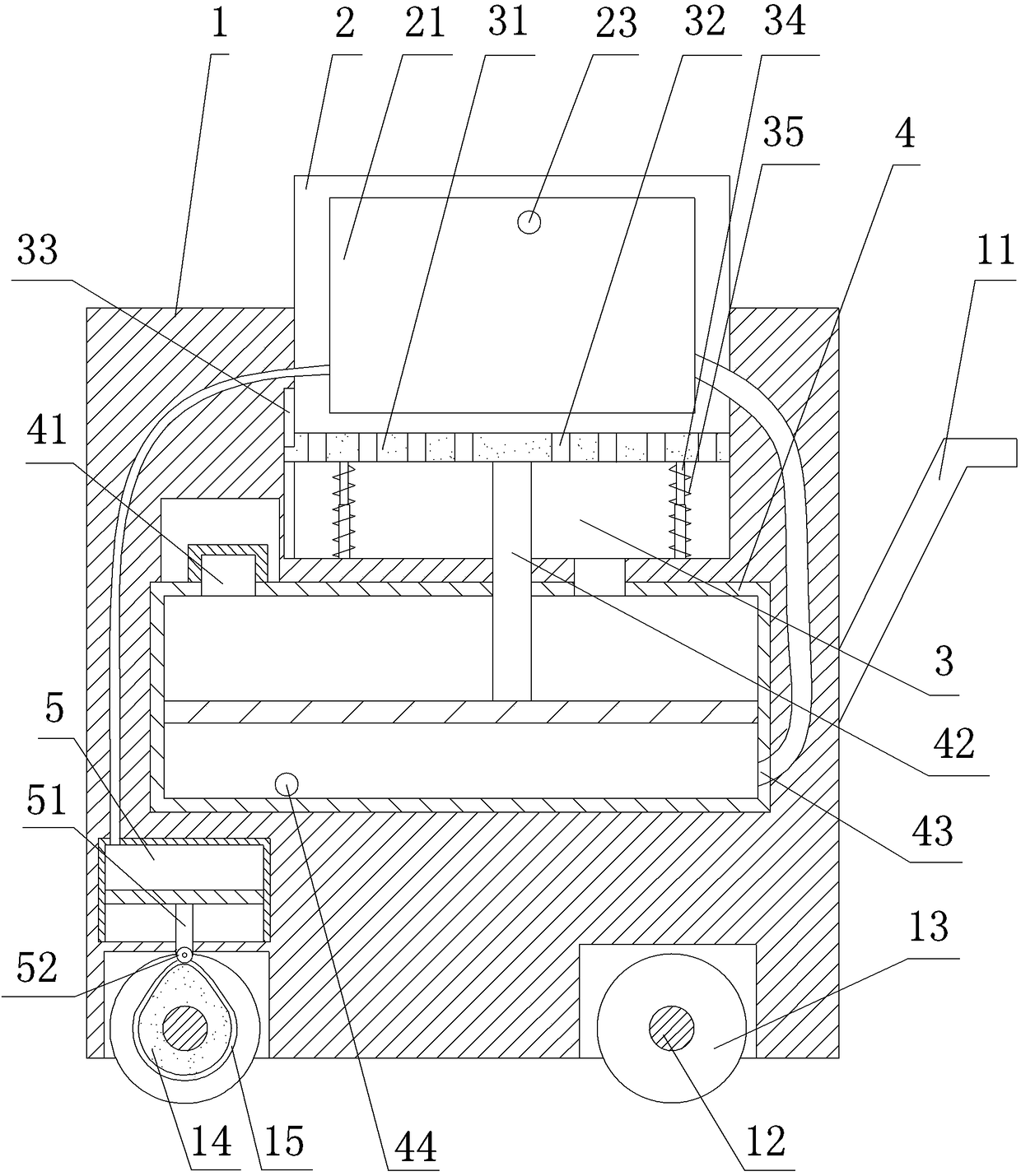
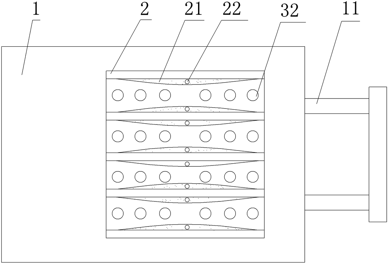
The invention relates to the field of production of circuit boards, and particularly discloses a circuit board transporting device. The circuit board transporting device comprises a fixed mechanism, avehicle body and vehicle wheels, and a push handle is fixed to the side wall of the vehicle body; an accommodation cavity is formed in the vehicle body, and is internally provided with a baseboard, athrough hole is formed in the baseboard, and a reset spring is arranged in the vehicle body; a negative pressure air cylinder is arranged below the baseboard, a liquid outlet is formed in the negative pressure air cylinder, a push rod is fixed to a piston of the negative pressure air cylinder, and the negative pressure air cylinder is communicated with the accommodation cavity; a vibration air cylinder is fixed into the vehicle body, and a vibration rod is fixed to the piston of the vibration air cylinder; the fixed mechanism comprises a partition plate and a gasbag, the partition plate is fixed to the baseboard, an air outlet one-way valve and an air inlet one-way valve are fixed to the side wall of the negative pressure air cylinder, an air outlet is formed in the gasbag, and the gasbagis communicated with the air outlet end of the air outlet one-way valve; a rotary shaft is arranged at the bottom of the vehicle body, and a cam is fixed to the rotary shaft. According to the scheme,liquid can be prevented from dripping on the bottom face.
Description
technical field [0001] The invention relates to the field of circuit board production, in particular to the field of circuit board production auxiliary tools. Background technique [0002] Circuit board, also known as printed circuit board, can gather a large number of electrical components together and provide them with electrical connections, and is an essential part of electronic components. At present, most of the circuit board production and processing are made by advanced etching process. First, the electronic board that needs to be preserved, that is, the graphic part of the circuit, is coated with a layer of aluminum tin layer for protection, and then the unnecessary place is etched by corrosion. Erosion, this processing method is etching technology. The etching process is divided into dry etching and wet etching. When wet etching is used, the etching solution still remains on the processed circuit board. During the process of transferring the circuit board to anoth...
Claims
Login to View More Application Information
Patent Timeline
 Patent Type & Authority Applications(China)
IPC IPC(8): B62B3/04B62B5/00
CPCB62B3/04B62B5/00
Inventor 王健
Owner 宁波隆锐机械制造有限公司
Features
- R&D
- Intellectual Property
- Life Sciences
- Materials
- Tech Scout
- Unparalleled Data Quality
- Higher Quality Content
- 60% Fewer Hallucinations
Learn More Browse by: Latest US Patents, China's latest patents, Technical Efficacy Thesaurus, Application Domain, Technology Topic, Popular Technical Reports.
© 2025 PatSnap. All rights reserved.Legal|Privacy policy|Modern Slavery Act Transparency Statement|Sitemap|About US| Contact US: help@patsnap.com


