Light conductive board and the backlight module possessing same

A backlight module and light guide plate technology, applied in the optical field, can solve problems such as poor picture resolution, increased display cost, and high power consumption

Inactive Publication Date: 2008-04-23
IND TECH RES INST
View PDF13 Cites 12 Cited by
  • Summary
  • Abstract
  • Description
  • Claims
  • Application Information

AI Technical Summary

Problems solved by technology

However, when applying this patented technology, an additional light source alignment design must be proposed; moreover, this design also has the problems of difficulty in manufacturing and difficulty in controlling manufacturing errors, resulting in poor light uniformity
[0009] Furthermore, when traditional LCDs display dynamic images, blurred afterimages are often found. As far as the designs of the above-mentioned patented technologies are concerned, most of them solve

Method used


Image

  • Light conductive board and the backlight module possessing same
  • Light conductive board and the backlight module possessing same
  • Light conductive board and the backlight module possessing same

Examples


no. 1 example

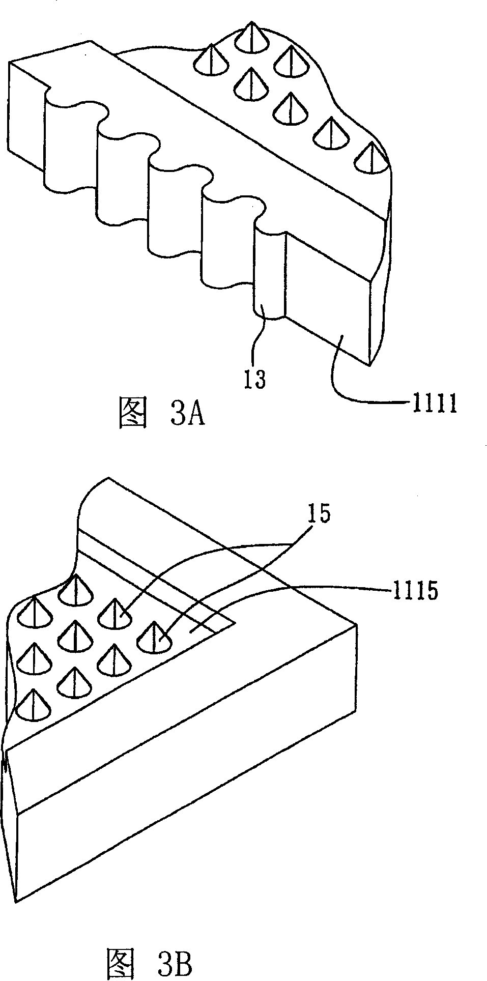
[0033] 1A to 3B are drawings drawn according to the first embodiment of the light guide plate of the present invention, Figure 4 is a schematic diagram showing the structure of a backlight module to which the light guide plate according to the first embodiment of the present invention is applied.

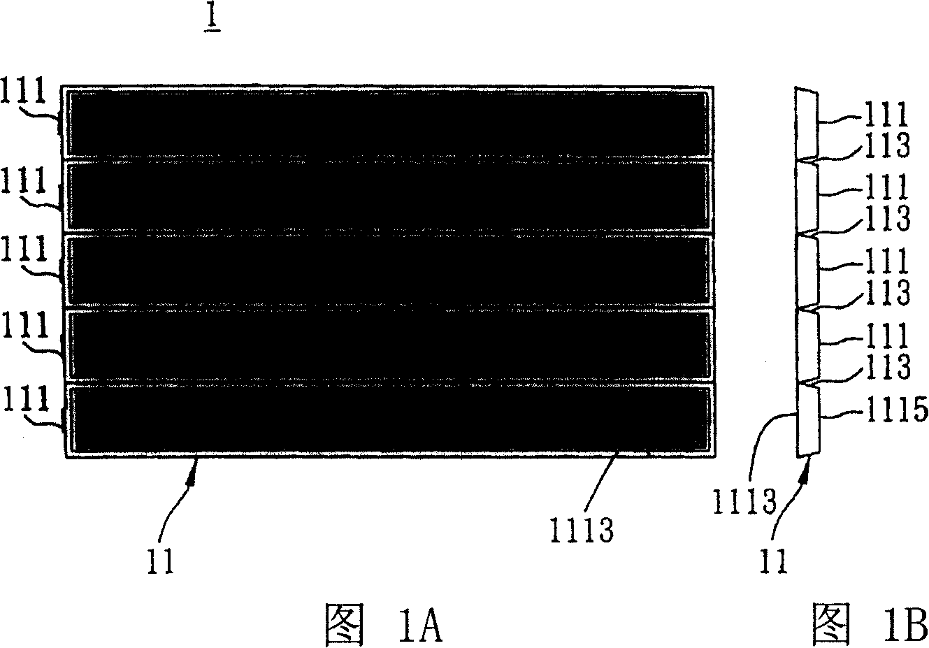
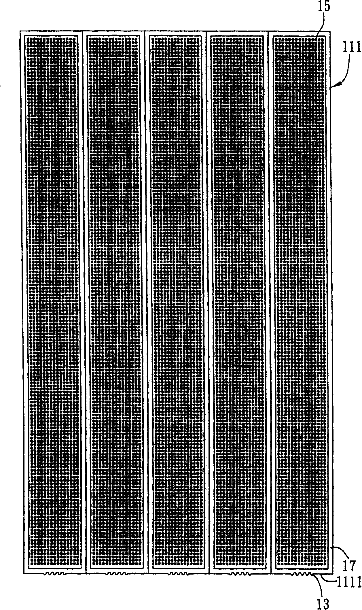
[0034] Please refer to Figure 1A, Figure 1B and figure 2 , they are schematic diagrams showing the structure of the light guide plate of this embodiment, wherein Fig. 1A and Fig. 1B are schematic diagrams showing the structure of the first embodiment of the light guide plate of the present invention, and Fig. 1B is a side view of Fig. 1A, figure 2 It is a schematic diagram showing a partial bottom view 1A of the light guide plate. As shown in the figure, the light guide plate 1 includes a light-transmitting substrate 11 , a grating structure 13 , and a light-scattering structure 15 .

[0035] The light-transmitting substrate 11 has a timing spacer 113 that divides the light-transm...

no. 2 example

[0051] Figure 5A to Figure 7 The drawings are drawn for the second embodiment of the light guide plate and the backlight module with the light guide plate according to the present invention. Wherein, the same or similar elements as those of the first embodiment are represented by the same or similar element symbols, and detailed descriptions are omitted to make the description of this case clearer and easier to understand.

[0052] The biggest difference between the second embodiment and the first embodiment is that in the first embodiment, multiple timing intervals are provided on the light-transmitting substrate to distinguish the light-transmitting substrate into multiple regions, while in the light guide plate of the second embodiment, The light-transmitting substrate is composed of a plurality of regions arranged at intervals.

[0053] Such as Figure 5A The shown light guide plate 1' includes a light-transmitting substrate 11' composed of five regions 111'. Such as ...


PUM


Abstract

The invention is a backlight module comprising a transparent substrate partitioned into multi areas, a grating structure located at the incident face of each area, and astigmatism structure of optical face used for receiving the incident light. The transparent substrate can be used to make partition sequential scan so as the grating structure can shorten the light-mixing distance; said astigmatism structure can evenly scatter the light out of the light-guiding plate.

Description

technical field [0001] The invention relates to an optical technology, in particular to a light guide plate applied to a backlight module and a backlight module with the light guide plate. Background technique [0002] Due to the continuous improvement of technology in recent years, the new generation of digital products can not only come from the technologies of the three major fields of information, consumption and communication, but also have the characteristics of multimedia performance. In this feature, image processing technology has gradually become a development area that attracts consumers' attention along with the maturity of various component technologies and increasing application areas. Fueled by the sharp increase in demand for imaging applications, there are more and more digital products with various overall display functions, which relatively makes the demand for displays also increase significantly. Among them, the most eye-catching one is Liquid Crystal Di...

Claims


Application Information

Patent Timeline
IPC IPC(8): G02B6/00G02F1/1335
Inventor 黎育腾杨政霖曲昌盛陈秀香伍清钦
Owner IND TECH RES INST
Why Eureka
Try Eureka