Brush holder in electric motor

A technology of electric motors and brush holders, which is applied in the direction of electric components, electromechanical devices, electrical components, etc., can solve the problems of light weight, miniaturization, increased outer diameter of the yoke or housing, and low production efficiency, etc., to achieve miniaturization The effect of increasing the degree of freedom of design and improving the assembly

Inactive Publication Date: 2008-04-23
MITSUBA CORP
View PDF1 Cites 10 Cited by
  • Summary
  • Abstract
  • Description
  • Claims
  • Application Information

AI Technical Summary

Problems solved by technology

[0005] However, in the above-mentioned conventional structure, it is necessary to form a concave portion for fitting the protrusion on the outer periphery of the yoke or the case, so the outer diameter of the yoke or the case increases, which is contrary to light weight and miniaturization. The problem
Moreover, in this structure, it is necessary to fit a tubular elastic member to each protrusion formed in the circumferential direction, so the operation is troublesome and the production efficiency is low. This is the problem to be solved by the present invention.

Method used


Image

  • Brush holder in electric motor
  • Brush holder in electric motor
  • Brush holder in electric motor

Examples


Embodiment Construction

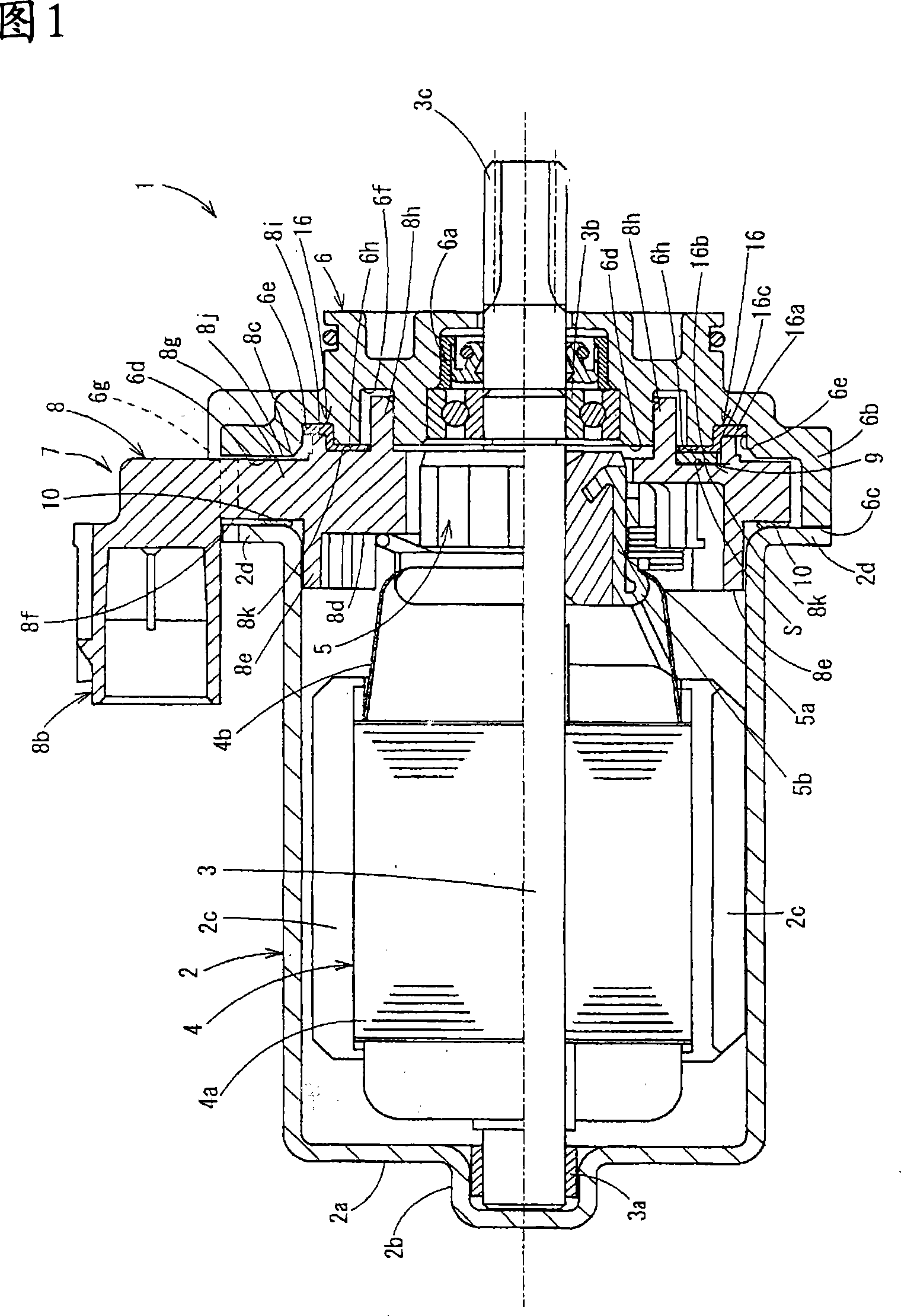
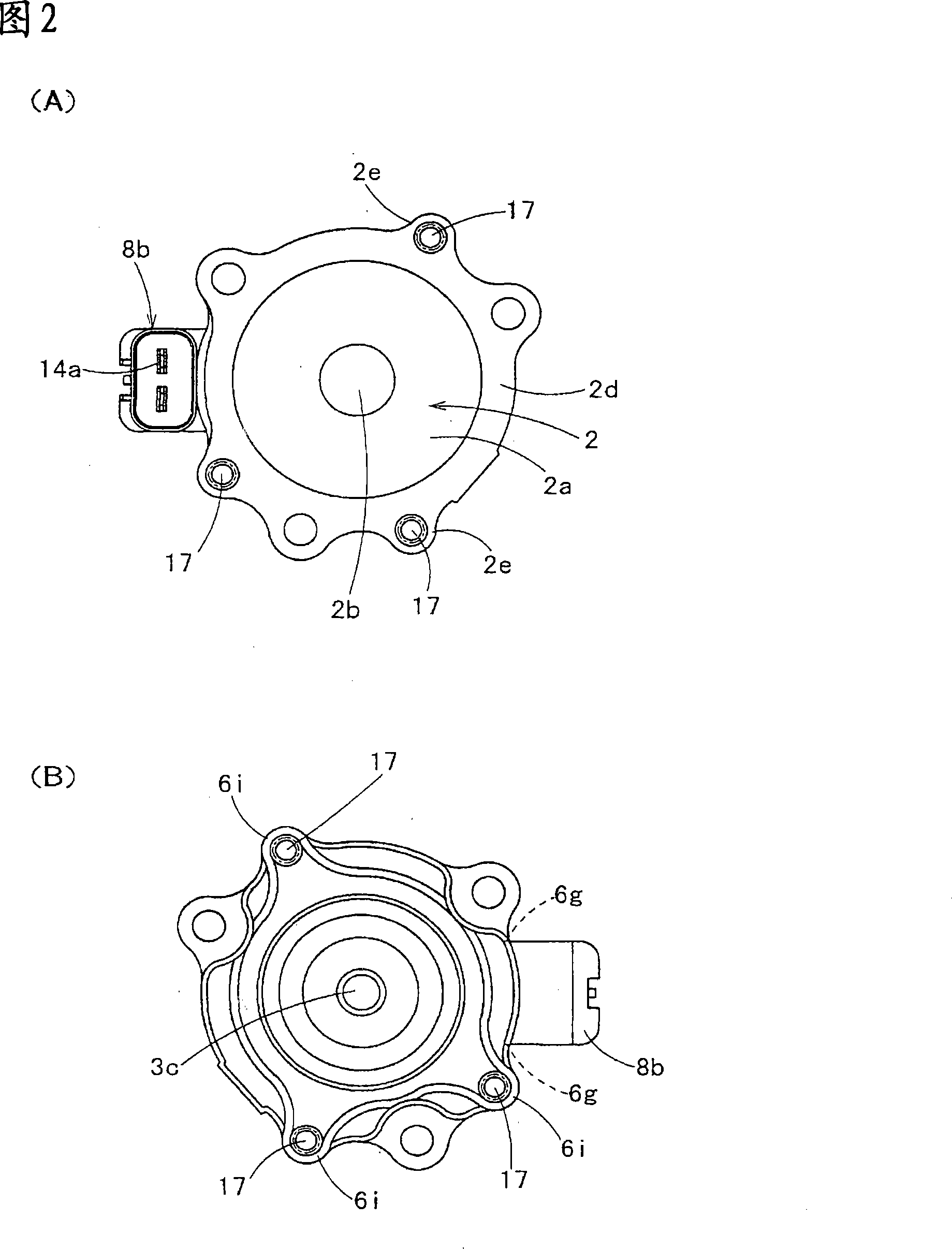
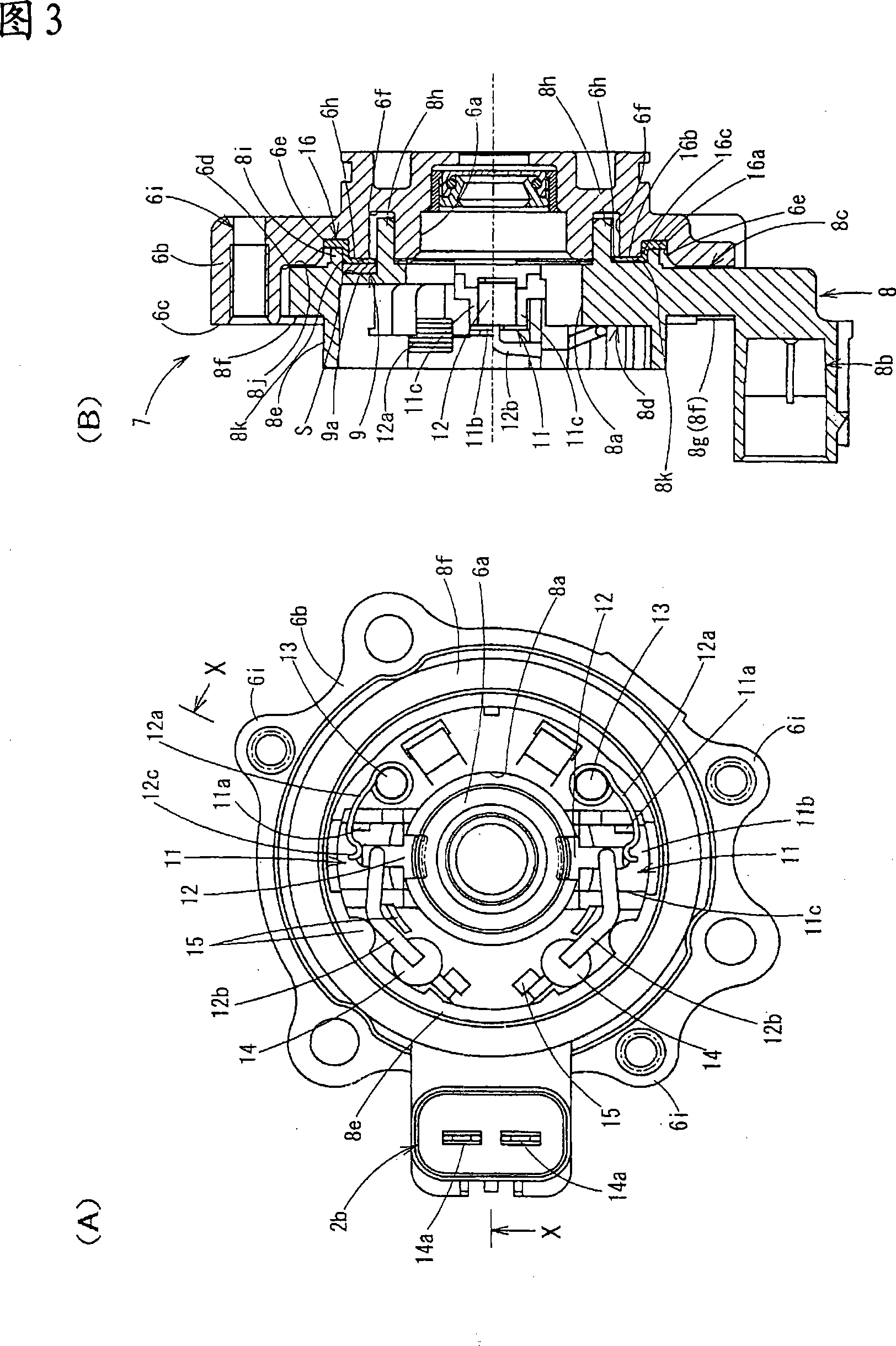
[0027] Hereinafter, embodiments of the present invention will be described with reference to the drawings.

[0028] In the drawing, reference numeral 1 denotes an electric motor constituting an electronic component mounted on a vehicle. A bearing portion 2b is formed on a cylindrical bottom portion 2a of a bottomed cylindrical yoke 2 constituting the electric motor 1, and passes over the bearing portion 2b. The base end portion of the motor shaft 3 is rotatably supported by the bearing 3a. A core 4 formed by laminating a plurality of core materials 4 a is integrally fitted to the motor shaft 3 , and a plurality of coils 4 b are wound around the core 4 . Further, the commutator 5 is integrally externally fitted to the motor shaft 3 so as to be located on the front end side of the coil 4 , and is provided in the circumferential direction on the commutator vertical pieces 5b of the plurality of commutator pieces 5a on the outer peripheral surface of the commutator 5 . , the ends...


PUM


Abstract

A brush holder in an electric motor, held between a tubular yoke with a bottom and a bracket that covers an opening of the yoke, and constructed to be small in diameter and compact. The brush holder (7) is composed of a first disk (8) where a three-sided section (11b, 11c) of a brush reception section (11) is formed, and of a second disk (9) where a bottom section of the brush reception section is formed. A ring-like contact surface (8k) is formed on the bracket (6) side of the brush holder (7), and the contact surface (8k) is formed by the first and second disks (8, 9) and includes the bottom section of the brush reception section (11). Between the contact surface (8k) and a bore side disk surface (6h) of the bracket (6) are interposed an outer diameter-side section (16a), a bore side section (16b), and a bracket-side elastic member (16) having a connection section (16c) for connecting the outer diameter side section (16a) and the bore side section (16b).

Description

technical field [0001] The present invention relates to a brush holder in an electric motor constituting an electric component or the like mounted on a vehicle. Background technique [0002] Such an electric motor generally has a configuration in which a brush holder having a disk portion forming a brush accommodating portion is sandwiched between a bottomed cylindrical yoke and a bracket that covers the opening of the yoke. between. In the case of such a configuration, it is necessary to prevent the brush holder from rotating or dislocating with respect to the yoke or the bracket. Therefore, there is a method of integrating the three parts using a fixing method such as a screw, but this method is not only troublesome but also complicated to assemble. , and there are problems such as an increase in working hours or an increase in the number of parts. [0003] As an improvement measure, it is proposed to integrate the brush holder, the yoke, and the bracket by a fixing meth...

Claims


Application Information

Patent Timeline
Patent Type & Authority Applications(China)
IPC IPC(8): H02K5/14H02K13/00
CPCH02K5/148
Inventor 山本勉近藤纯
Owner MITSUBA CORP
Why Eureka
Try Eureka