Manipulator for medical use

A manipulation device, medical technology, applied in applications, medical science, surgical fixation nails, etc., can solve problems such as slow recovery of patients

Active Publication Date: 2008-04-30
KARL STORZ GMBH & CO KG
View PDF2 Cites 10 Cited by
  • Summary
  • Abstract
  • Description
  • Claims
  • Application Information

AI Technical Summary

Problems solved by technology

Large incisions become the cause of infection or slow the patient's recovery

Method used


Image

  • Manipulator for medical use
  • Manipulator for medical use
  • Manipulator for medical use

Examples


Embodiment Construction

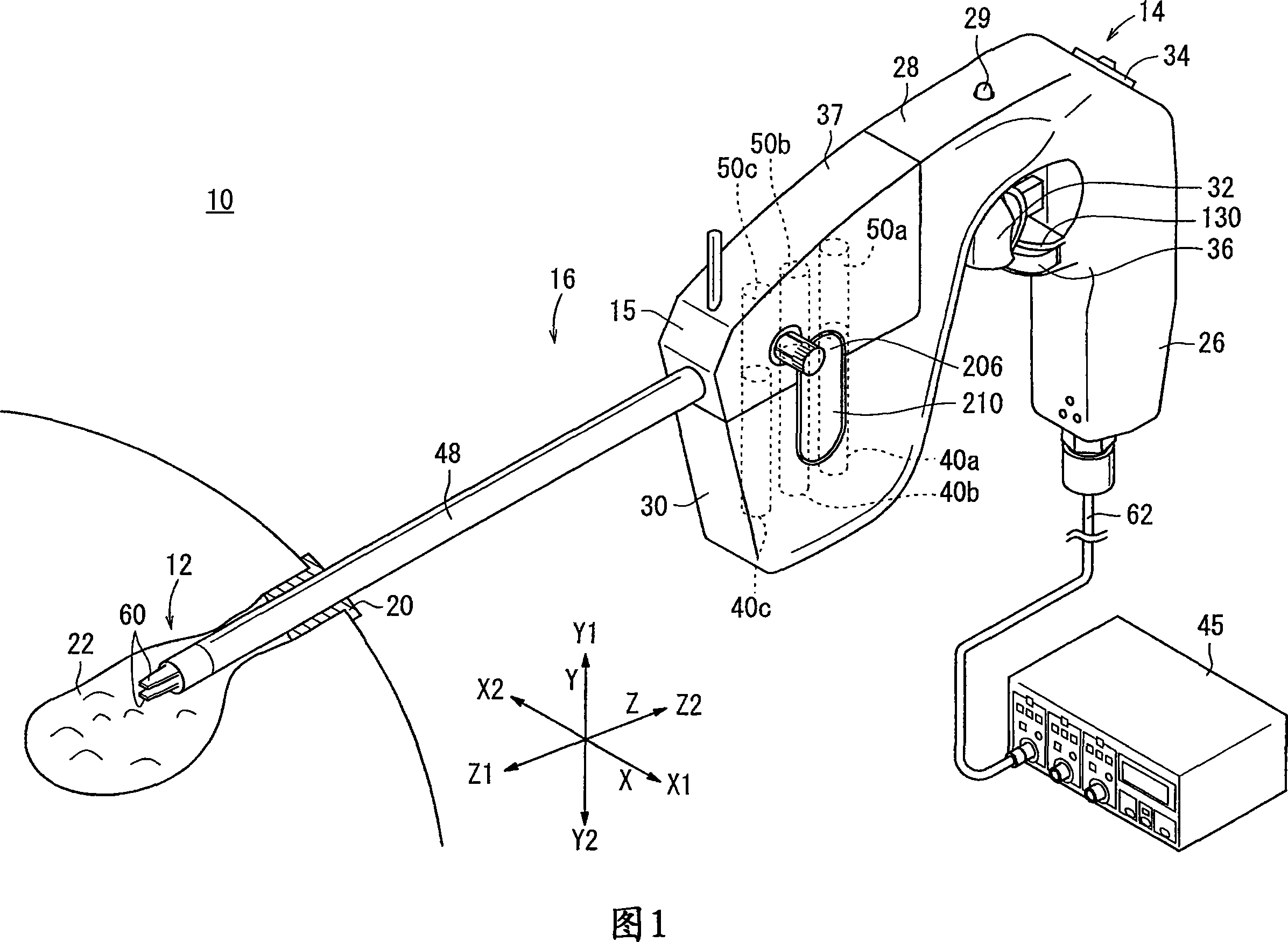
[0044] Hereinafter, an embodiment of the medical manipulation device of the present invention will be described with reference to FIGS. 1 to 21 .

[0045] The manipulator 10 of the first embodiment is an instrument for performing a predetermined treatment by grasping a part of a living body or a curved needle by the distal operating part 12, and is generally called grasping forceps or a needle driver (needle holder).

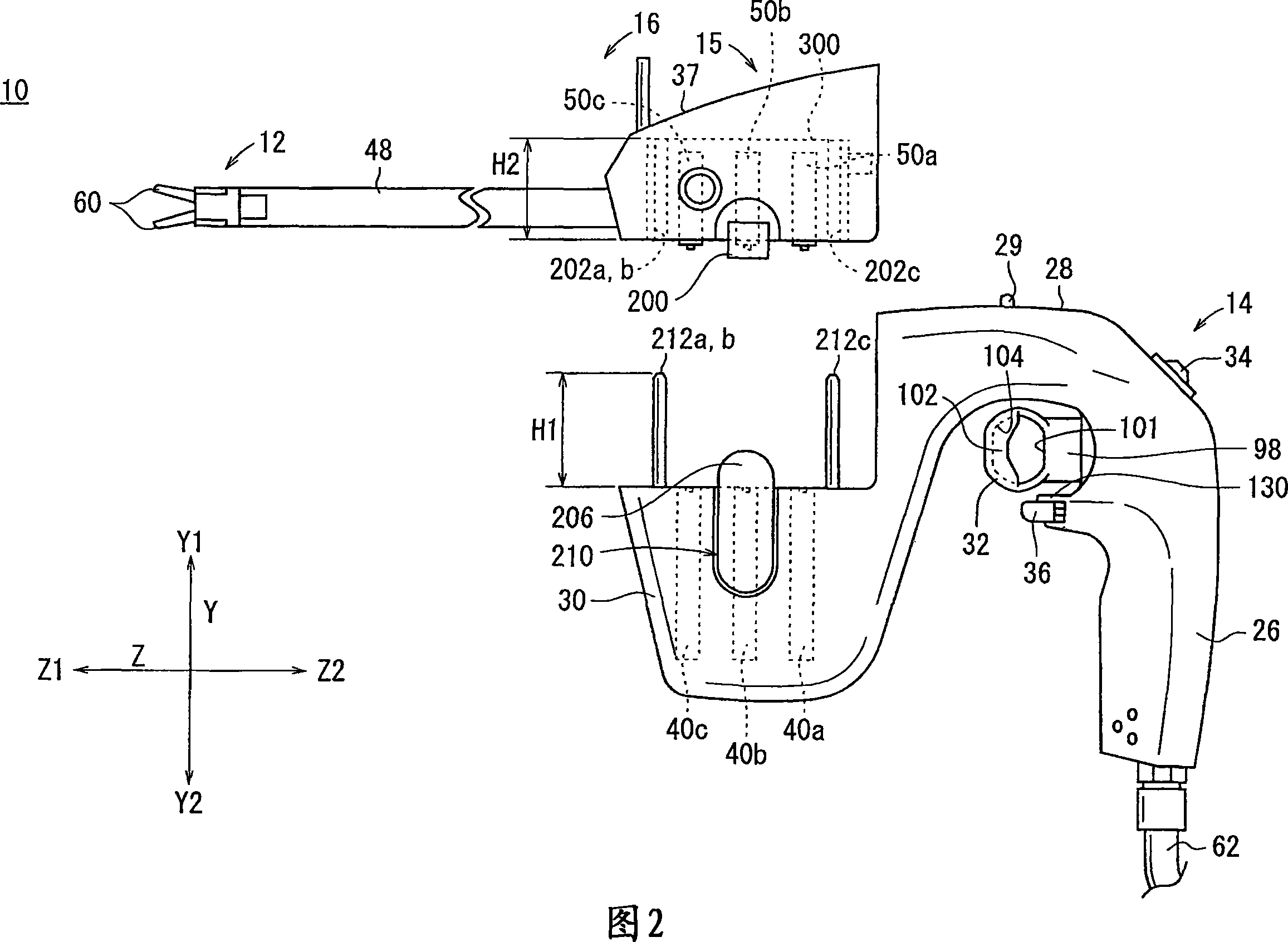
[0046] As shown in FIG. 1 and FIG. 2 , the manipulation device 10 has an operation instruction unit 14 at a base end portion that is grasped and operated by a human hand, and a working unit 16 that is detachable from the operation instruction unit 14 .

[0047] In the following description, the width direction in FIG. 1 is defined as the X direction, the height direction is defined as the Y direction, and the direction of the extension line of the connecting shaft 48 is defined as the Z direction. In addition, it is prescribed that the right side is the X1 direc...


PUM


Abstract

In a manipulator (10), an actuator block (30) contains motors (40a to 40c) and rotary shafts (42a to 42c) extending from the motors (40a to 40c). A working unit (16) of the manipulator (10) contains a connecting portion (15), attachable to and detachable from the actuator block (30). The connecting portion (15) has pulleys (50a to 50c) connectable to ends of the rotary shafts (42a to 42c), and has a locking plate (304) movable by alignment pins (212a to 212c). The locking plate (304) has slits (316a to 316c), which are engaged with plate-shaped portions (308a to 308c) formed on the upper ends of the pulleys (50a to 50c). A coil spring (306) is placed between the locking plate (304) and a top plate (334).

Description

technical field [0001] The present invention relates to a medical manipulation device in which a working portion is detachable from an actuator. Background technique [0002] In laparoscopic surgery, several small holes are made in the patient's abdomen and an endoscope, forceps (or manipulator), etc. are inserted into the hole, and the operator performs the operation while observing the image of the endoscope through a monitor. Since such laparoscopic surgery does not require an open laparotomy, the burden on the patient is reduced, and the postoperative recovery and the number of days to discharge are greatly reduced. Therefore, it is expected that the field of its application will be further expanded. [0003] The manipulator system is as described in JP 2004-105451 A, and is composed of a manipulator main body and a controller for controlling the manipulator main body. The manipulator main body is composed of an operation part operated manually and a working part that c...

Claims


Application Information

Patent Timeline
Patent Type & Authority Applications(China)
IPC IPC(8): A61B17/00A61B17/94A61B1/00A61B19/00
CPCA61B2017/00477A61B2017/0046A61B19/22A61B2019/4857A61B2019/2249A61B34/70A61B34/72A61B2090/0811
Inventor 大森繁上之原秀一神野诚砂押贵光
Owner KARL STORZ GMBH & CO KG
Why Eureka
Try Eureka